
Convert FBX to STL for 3D Printing: Step-by-Step Guide
You've got an FBX model that looks finished in a viewer, but your slicer needs an STL. After conversion, the character is grey, the base is tiny, and the model lands on its side. The file opens, yet it's nowhere near ready to print.
To convert FBX to STL reliably, treat the export as a manufacturing handoff, not a filename change. Choose the geometry you need, establish its physical size, and inspect the resulting surface before committing filament or resin.
Table of Contents
- What Survives FBX to STL Conversion
- Find the Right Scale Before Export
- Export an FBX as STL in Blender Step by Step
- Check Mesh Validity Before You Print
- Troubleshoot a Conversion That Fails
- Decide What to Keep and Test One Model
What Survives FBX to STL Conversion
A rigged character can arrive in your slicer as a plain grey shape even when the conversion worked correctly. The exported surface survived; the clothing textures, skeleton, and animation didn't.
FBX is a scene format, while STL is a surface format. The FBX format overview describes its roots in motion-capture workflows and its ability to carry information beyond polygon geometry. That's why a convincing rendered asset isn't automatically a printable object.
What survives FBX to STL conversion
| FBX element | Kept in STL? | What to do |
|---|---|---|
| Triangle mesh geometry | Yes | Apply modifiers and check the mesh before export |
| Separate objects | Yes, but may be merged | Join only the parts that should print as one piece |
| Materials and textures | No | Export a GLB or OBJ alongside if colour matters |
| Rig and skeleton | No | Export the mesh in its rest or bind pose |
| Animation keyframes | No | Choose one frame that shows the intended shape |
| Cameras and lights | No | Delete them from the selection before export |
| Unit metadata | No | Set the scale explicitly using a measured reference |
Separate objects deserve particular attention. Their triangles can remain as disconnected shells, but STL doesn't retain the original object hierarchy. Joining objects in Blender also doesn't fuse their intersecting surfaces into a clean solid.
For format selection beyond printing, the Blender file formats guide provides useful context. If your starting material is a technical drawing rather than an existing mesh, American Additive Manufacturing's resource to convert 2D drawings to 3D models addresses that earlier modeling step.
Practical rule: Approve the untextured silhouette before export. If an important feature exists only in a texture, it won't become printable relief by changing formats.
Find the Right Scale Before Export
A model that fills the Blender viewport can still be far too small on the slicer's build plate. Viewport framing tells you nothing about physical dimensions.
The Printpal FBX-to-STL guide identifies 10× size errors caused by unit mismatches: FBX can declare scene units, while STL lacks unit metadata and slicers commonly interpret coordinates as millimetres. A converter can therefore report success without producing the size you intended.
Start by selecting the object and opening Blender's Item panel, then inspect Dimensions. Check Scene Properties → Units as well, but don't assume changing the displayed unit system alone repairs incorrectly sized geometry.
Establish a Measured Reference
Use a feature with a known physical size: the width of a mounting plate, the diameter of a hole, or the height specified in a drawing. If the asset is purely decorative, choose the desired finished height and size it deliberately.
The table shows unit arithmetic, not a universal export preset. Its worked examples are hypothetical.
Scale factors to reach millimetres
| Source unit | Factor to millimetres | Worked example |
|---|---|---|
| Metres | 1000 | For example, 0.05 m becomes 50 mm |
| Centimetres | 10 | For example, 5 cm becomes 50 mm |
| Inches | 25.4 | For example, 1 inch becomes 25.4 mm |
| Millimetres | 1 | For example, 50 mm stays 50 mm |
| Unknown | Target measurement divided by current measurement | Measure a known feature before choosing a factor |
Apply the conversion once. Either resize the object so its exported coordinates represent the intended millimetres, or use the exporter's Scale field. If you resize the object and also enter the same conversion factor during export, you'll multiply the correction twice.
When units are unknown, calculate the ratio between the required measurement and the current measurement using the same unit for both. Don't choose a factor because the model looks plausible beside the grid.
Check Orientation Independently
After sizing, identify the face that should contact the build plate. Confirm the model's height and footprint rather than relying on the camera angle.
An axis correction and a print-orientation decision aren't interchangeable. First preserve the intended coordinate orientation during export; then position the part in the slicer for stability, supports, and surface quality.
Export an FBX as STL in Blender Step by Step
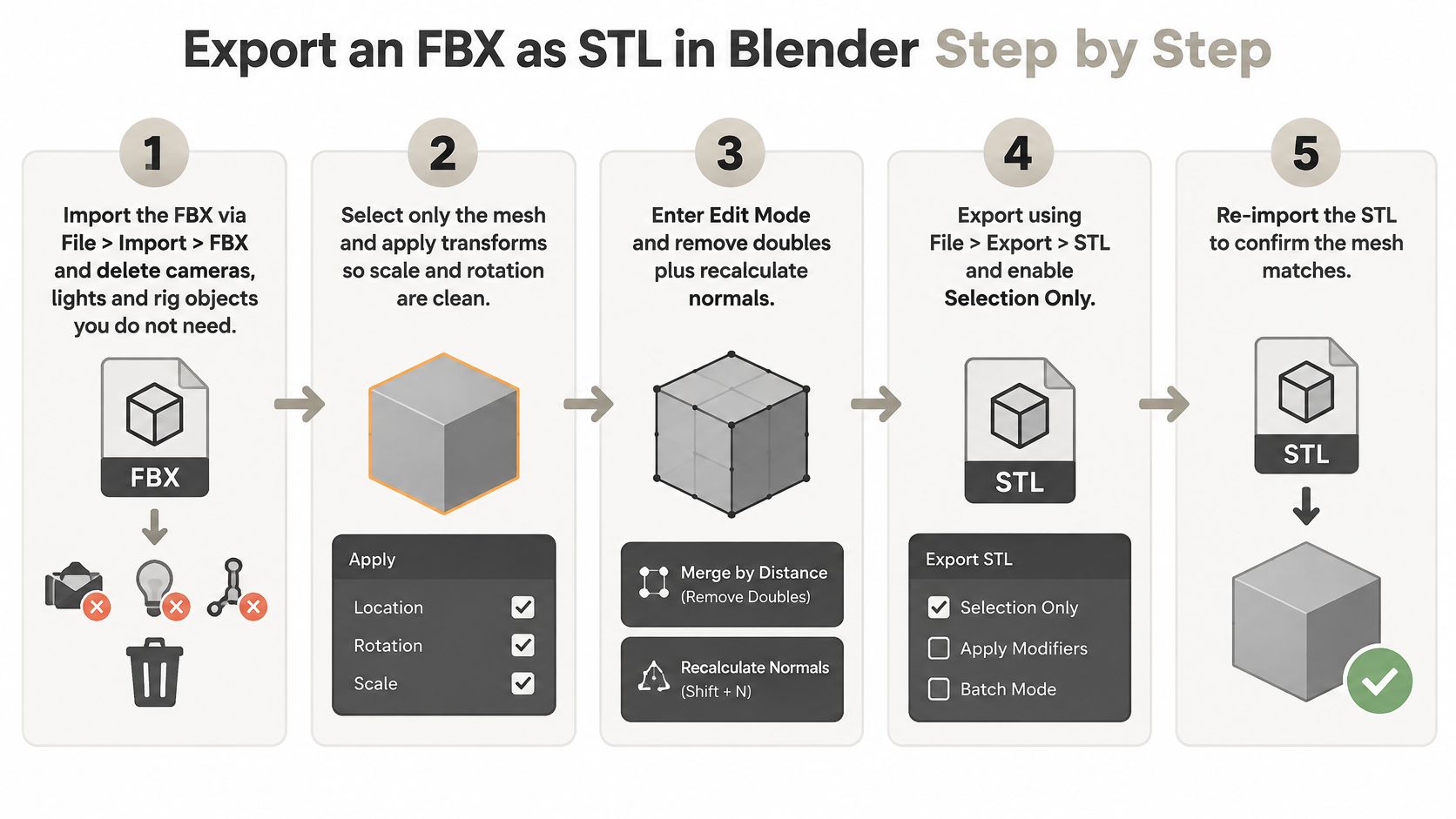
Work on a duplicate of the imported asset so you can repair the printable version without damaging the editable master. The Blender STL export documentation explains the export controls, including evaluated modifiers, scale, and axis mapping.
This visual summarises the import, cleanup, export, and verification sequence.
Prepare the Printable Mesh
Import the source. Choose File → Import → FBX, then inspect the Outliner for meshes, cameras, lights, and armatures. For a posed character, preserve the evaluated pose before deleting its armature; removing a rig prematurely can change the shape.
Select the intended parts. Isolate the printable mesh and inspect it from behind and underneath. Don't rely on viewport visibility alone to define the export selection, especially when the source includes alternate clothing, accessories, or duplicate bodies.
Apply rotation and scale. In Object Mode, use Ctrl+A → Rotation & Scale after establishing the intended dimensions. This makes subsequent modeling operations more predictable, but it doesn't independently solve a unit mismatch.
Inspect topology in Edit Mode. Use Merge by Distance to weld coincident vertices, then inspect open boundaries and recalculate outward normals. Keep the merge distance conservative so nearby intentional details don't collapse together.
Confirm scene units and record dimensions. Check Scene Properties → Units, then write down the object's bounding-box dimensions and a reference feature measurement. The common slip is trusting a unit label without checking the actual object size.
Export and Reopen the Result
Open File → Export → STL. Use the settings below, checking the available labels in your Blender version. A preview that includes subdivision or Solidify can differ substantially from the exported base mesh if modifier evaluation is disabled.
Save, then re-import the STL into a clean scene. Compare its dimensions and silhouette with your recorded reference, then open it in the slicer. Keep the imported STL separate from the source so overlapping copies don't hide missing surfaces.
Blender STL export settings
| Setting | Set to | Why it matters |
|---|---|---|
| File format | Binary | Smaller files and the standard choice for production |
| Apply Modifiers | On | Exports subdivision, mirror, and solidify results rather than the base mesh |
| Selected Only | On | Exports only the printable selection and leaves out stray parts |
| Scale | Factor from the scale table, unless already corrected | Prevents unit mismatch without applying the correction twice |
| Forward and Up axes | Test orientation and a known dimension | Avoids an unintended coordinate rotation |
| ASCII | Off | Reserve text output for debugging or interoperability checks |
For interface details and further export context, use the Blender STL format guide. A good first export has the intended object or assembly, the expected outline, and no unexplained slicer warnings.
For a video walkthrough alongside the written procedure, use this demonstration.
Check Mesh Validity Before You Print
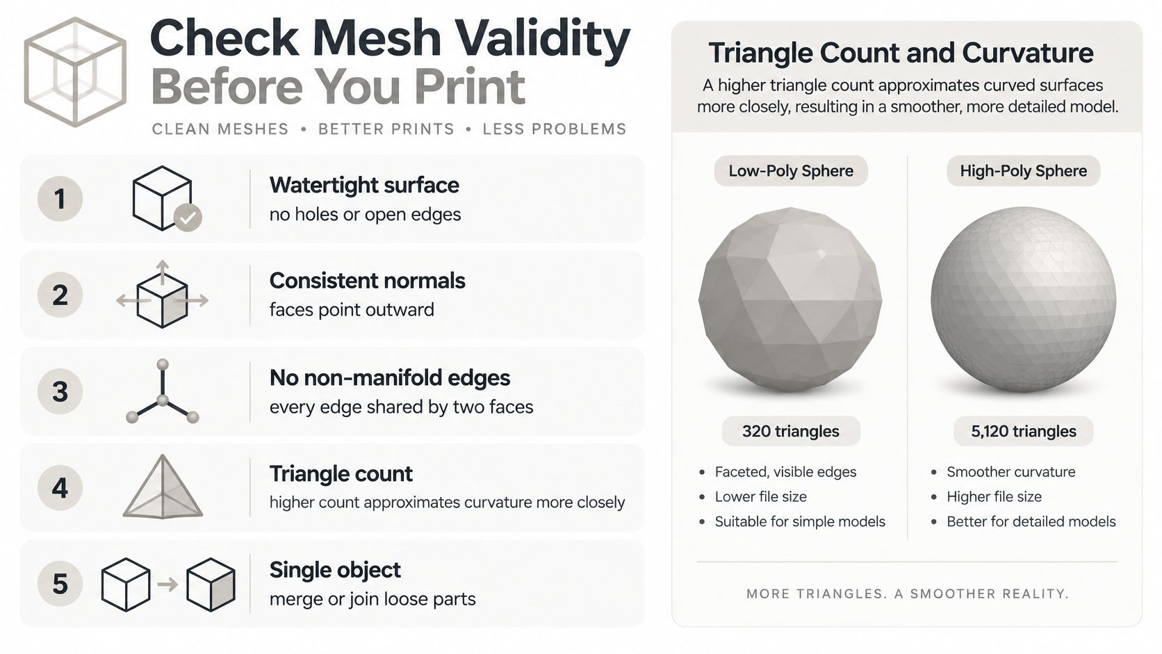
A smooth shaded viewport can hide a coarse or broken mesh. STL stores flat triangular facets, so curved surfaces are approximations, not mathematical curves. The STL technical specification hosted by Carnegie Mellon describes that surface representation and its connectivity requirements.
Increase tessellation where the printed outline needs it, not everywhere by default. Coarse curves leave visible facets; excessive density makes editing and slicing harder without necessarily improving the physical result.
Use this checklist while inspecting the exported surface.
Inspect the Surface, Not Just the Appearance
- Open boundaries: Find unintended holes and cap them with suitable topology. Don't blindly fill deliberate openings such as a cup's mouth; a printable cup needs connected inner and outer walls, not a sealed top.
- Non-manifold regions: Inspect branches, shared internal faces, and ambiguous intersections. The non-manifold geometry guide helps distinguish these defects from ordinary disconnected objects.
- Duplicate vertices: Weld vertices that should form a continuous surface. Leaving coincident but unconnected boundaries can preserve cracks that aren't obvious in solid shading.
- Disconnected shells: Examine loose eyes, teeth, accessories, and hair surfaces. Remove unwanted fragments or connect intended features with actual material.
- Inverted normals: Recalculate outside and inspect suspicious areas manually. A consistent outward-facing surface helps downstream tools interpret the enclosed volume.
- Internal geometry: Remove trapped faces and resolve overlapping solids where a continuous body is required. A Boolean union or remesh can help, but inspect the result for lost details.
- Thin sections: Measure fingers, blades, hair, and walls against your printer and material settings. A surface with no thickness needs geometry added, not merely a repair warning dismissed.
Joining loose objects isn't a substitute for making them printable. Likewise, remeshing can close gaps but soften lettering, round sharp edges, or alter fitting surfaces.
A watertight mesh is a geometry milestone, not permission to skip the slicer preview.
Inspect the layers through thin features, cavities, and repaired areas. Confirm that expected walls generate toolpaths and that no unexplained islands appear.
Troubleshoot a Conversion That Fails
Start with size when the model looks wildly wrong in the slicer. Compare its displayed dimensions with your intended measurements before touching repair tools. A topology repair won't correct a unit mismatch.
Separate export-setting failures from geometry failures. Selection, modifier evaluation, and axis mapping call for a corrected export; holes, overlapping surfaces, and inadequate thickness require changes to the mesh.
Conversion symptoms, causes and fixes
| Symptom | Likely cause | Fix |
|---|---|---|
| Model far too small or large in the slicer | Unit mismatch | Apply the appropriate scale factor and re-export |
| Parts missing in the slicer | Modifiers not applied or hidden objects exported | Apply modifiers and export only the printable object |
| Holes or error warnings | Open edges or non-manifold regions | Repair in a mesh tool and fill unintended holes, then re-check |
| Model prints sideways or upside down | Up-axis mismatch | Change the Up axis and compare the bounding box with a known dimension |
| Curved surfaces look faceted | Coarse tessellation | Subdivide or remesh before export |
| File far larger than the model needs | Excessive triangle count | Decimate after repair, keeping the detail the print needs |
| Colours or textures missing | STL carries no materials | Export a GLB or OBJ alongside the STL |
Match the Fix to the Failure
For missing parts, reopen the source and check whether the feature is real geometry. A textured belt buckle won't appear as raised detail, while a buckle created by a modifier may need evaluation enabled. An unwanted hidden shell can also complicate the slicer's interpretation, so inspect the export selection directly.
For faceting, don't assume subdivision can recover detail that never existed. Simple subdivision adds faces without necessarily improving the outline, while smoothing subdivision changes the shape. Protect mounting surfaces and sharp edges before using it.
Budget for Another Validation Pass
Scale, selection, and axis changes are quick settings corrections, but they still need a fresh export and inspection. Remeshing and manual reconstruction take more attention because they can alter the geometry you're trying to preserve.
Decimate only after establishing a healthy surface, then compare the simplified version against the original silhouette and critical dimensions. If an automatic repair makes a model look inflated or erases a recess, undo it and repair the affected area more selectively.
Stop condition: Don't print a file with an unexplained warning simply because the slicer offers to continue.
Decide What to Keep and Test One Model
Use STL as the delivery file when the job needs static, validated geometry. Keep the original FBX as the editable master whenever future changes could involve pose, assembly structure, or appearance. A companion GLB or OBJ is useful for visual review, but it shouldn't replace the source asset.
The practical distinction is between a print deliverable and a reusable asset. You can approve the former without throwing away the latter. Store the source, repaired working file, and final export with clear names so you don't accidentally edit an outdated mesh.
Run an Acceptance Test
- Record the reference: Save the intended overall dimensions and a critical feature measurement before exporting.
- Compare the exported geometry: Re-import the STL into an empty scene and check size, orientation, and the features most vulnerable to repair or simplification.
- Inspect the sliced result: Look through the layers rather than judging only the solid preview. Confirm wall paths, connected features, and intentional cavities.
- Print a representative test: Choose a small part or section that includes the difficult feature, such as a socket, thin appendage, or repaired junction.
- Approve before batching: Confirm fit and surface quality, then keep the validated export settings with the project.
For a mechanical part, prioritise mating dimensions and hole fit. For a figurine, prioritise fragile details, attachment points, and the supported orientation. The acceptance criteria should match what would make the physical part unusable.
Don't let a successful download stand in for that decision. The useful result isn't merely an STL that opens; it's a file whose dimensions, surfaces, and sliced paths match the object you intend to make.
Sculpty offers browser-based model viewers, format converters, and remesh tools, with exports including STL, GLB, OBJ, and FBX. Visit Sculpty to prepare a printable copy while retaining a richer version of your asset, then validate that STL in your slicer before running a test print.