
Blender STL Format: Export Settings That Print
The usual advice to select a model and click Export STL skips the part that determines whether it will print. A polished Blender viewport isn't proof of a printable solid. Shading can hide a hole, a material can suggest detail that doesn't exist in the mesh, and a believable-looking miniature can arrive in the slicer at the wrong size.
Treat the Blender STL format as a disposable manufacturing handoff, not a saved asset. Keep an editable master, prepare a separate print mesh, and export binary STL only when its dimensions, outward-facing surfaces, and closed shell have survived inspection.
Table of Contents
- What an STL Export Keeps From Blender
- Export Settings Slicers Need From You
- Import and Export an STL Step by Step
- Scale Normals and Broken Shells
- Remesh Decimate and Repair the Mesh
- Decide Between the Print Mesh and the Master
What an STL Export Keeps From Blender
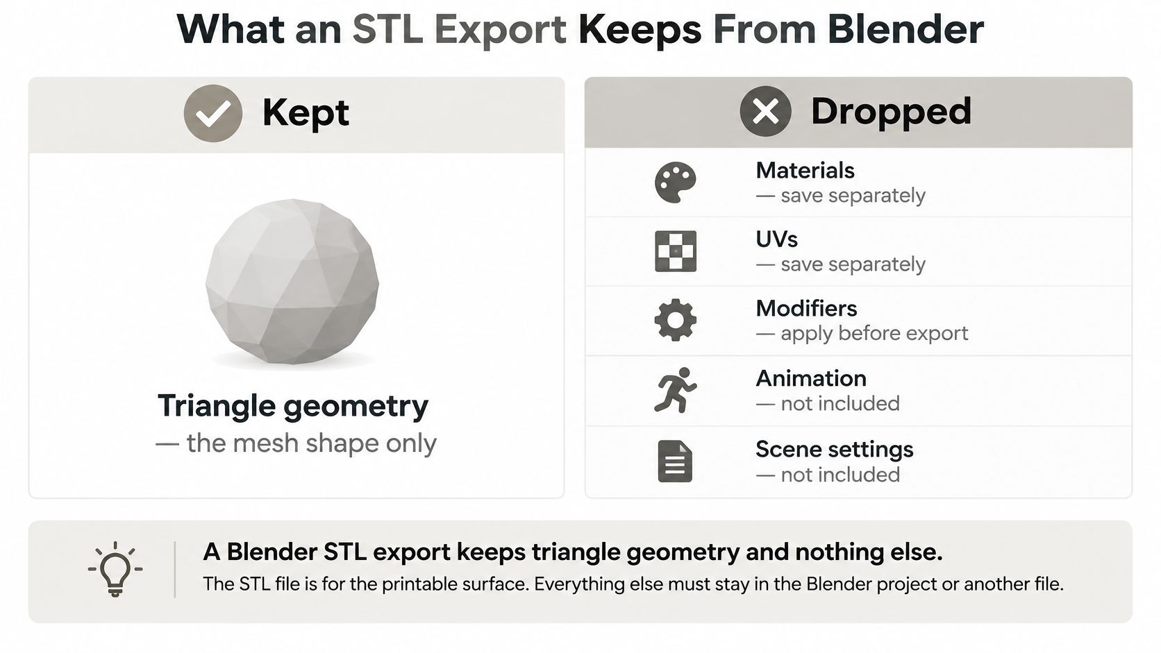
An STL export keeps triangle geometry, not the Blender asset around it. Use this distinction before deciding what to export or delete.
What survives an STL export from Blender
| Data | In an STL | Keep it in |
|---|---|---|
| Triangle surface | Yes, as facets | STL print mesh |
| Stored facet normal | Yes, one per triangle | Recalculate in Blender if the shell is wrong |
| Materials and PBR textures | No | GLB, FBX, USDZ, or the .blend |
| Cameras, lights, and world | No | .blend |
| Object hierarchy and animation | No | GLB, FBX, or USDZ |
| Scene units | No standard unit | Millimeter scene plus a slicer dimension check |
| Live modifiers | Only the evaluated result | .blend master |
Say you've built a figurine with convincing PBR skin and a live Solidify modifier on its clothing. Export its evaluated geometry, and the clothing's thickness can reach the slicer, but the skin material won't. The receiving application gets bare facets, with no editable Solidify control to adjust afterward.
If the figurine's pores exist only in a normal map, they won't become printed surface detail. Actual modeled displacement can survive when it becomes part of the evaluated mesh. That difference matters more than how detailed the render looks.
The comparison below separates the printable surface from the information that belongs in your project.
Surface geometry isn't an editable solid
The Library of Congress description of STL identifies its core representation as a tessellated surface made from triangles, rather than a parametric CAD solid. A curved cheek therefore becomes a collection of planar facets, not a mathematical surface you can adjust with a radius parameter.
That representation is useful for handing a shape to manufacturing software. It's less useful when you need to change the character's pose, revise clothing thickness, or restore a material assignment. Importing the STL into Blender doesn't reconstruct those authoring decisions.
Practical rule: Save the construction history before you export the construction result.
If you're choosing between mesh exchange formats, the STL versus OBJ comparison helps distinguish a geometry-only delivery from a workflow that needs additional asset information. Neither should replace the native project when you still need Blender-specific editing.
Keep the .blend as the editable master, retain a richer exchange copy such as GLB when useful, and label the STL as the fabrication handoff.
Export Settings Slicers Need From You
Start with these settings for a millimeter-based print workflow. The important qualification is that unit labels alone don't establish what coordinates the exporter writes.
Blender STL export settings for 3D printing
| Setting | Use this | If you skip it |
|---|---|---|
| File type | Binary STL | ASCII adds unnecessary file size for the same geometry |
| Scene units | Metric, millimeters, with an explicit coordinate convention | The slicer can interpret coordinates at the wrong physical size |
| Object scale | Apply Scale, then use export scale 1.0 | Unapplied transforms can complicate thickness and dimension checks |
| Forward / Up | Y Forward, Z Up | An unintended axis conversion can rotate the mesh relative to the bed |
| Modifiers | Export the evaluated mesh | Required Solidify or Mirror results can be omitted |
| Selection | Selected objects only | Spare meshes can contaminate the file |
| Batching | One closed body per STL unless separate shells are intentional | Overlapping objects can arrive without a valid union |
The Blender STL import and export manual describes binary STL as more compact than ASCII and documents controls for selection, evaluated modifiers, scale, scene units, and axis conversion. Use binary for routine transfer. ASCII is useful when you specifically need readable text, not as a print-quality upgrade.
Make the coordinate convention explicit
A practical convention is to model with millimeter-sized coordinates and export those coordinates unchanged. Set the scene to Metric, display lengths in Millimeters, and configure Unit Scale so a Blender coordinate unit represents a millimeter. With that convention, leave export scale at 1.0 and avoid applying a second scene-unit conversion that changes the numbers.
Alternatively, you can model with meter-based coordinates and deliberately convert during export. Both approaches can work. Mixing them is what produces a correctly labeled Blender object and an incorrectly sized STL.
Apply Scale with Ctrl+A → Scale before judging thickness-sensitive modifiers. This preserves the object's visible dimensions while normalizing its transform; it doesn't magically repair an incorrect physical size, and an unapplied transform doesn't automatically mean the exporter will distort the object.
A unit setting is a declaration. A matching dimension in the slicer is the proof.
Export the intended surface
Enable Apply Modifiers, or the equivalent evaluated-mesh option in your Blender version. Don't permanently apply the master's modifier stack just to satisfy the exporter. Check the print copy instead, especially when Subdivision could add facets without improving the printed silhouette.
Use Selection Only to exclude spare meshes, ground planes, and earlier versions. Lights don't become printable triangles, but an overlooked mesh backdrop certainly can.
Keep Y Forward and Z Up when you want Blender's orientation preserved. This doesn't choose the strongest print orientation for you. Bed placement, support access, and layer direction remain slicer decisions.
Import and Export an STL Step by Step
Use a fresh file to establish the workflow before handling a complicated scene. For a running example, suppose the miniature must finish 80 mm tall; that's a hypothetical design target, not a default import size.
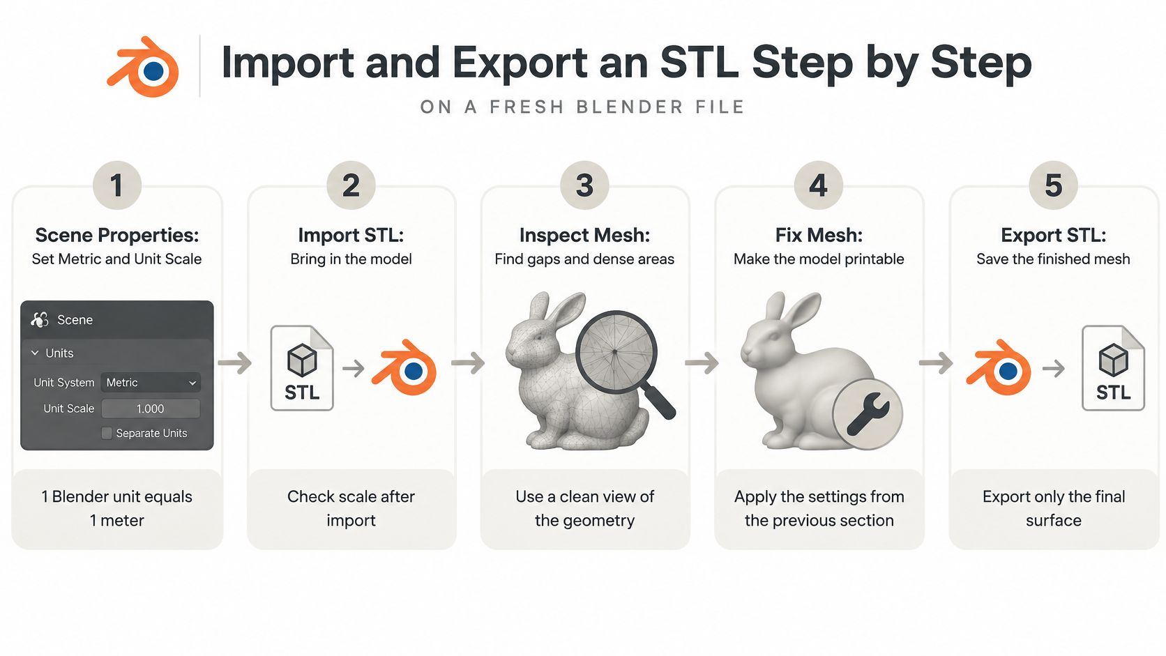
The workflow illustration gives an overview. For the procedure below, use a millimeter-coordinate convention rather than leaving the scene at its default meter interpretation.
Prepare the scene and inspect the source
Set the coordinate convention before importing, using Scene Properties → Units → Metric, Length Millimeters, and Unit Scale 0.001, so a coordinate unit represents a millimeter. Changing Length alone changes the display, not the underlying coordinate convention.
Import the incoming mesh through File → Import → STL, leaving import scale at 1, so you can inspect the file without an additional arbitrary multiplier. Press N, open Item, and compare Dimensions against the intended miniature height.
Correct the target dimensions deliberately, then apply scale, using Ctrl+A → Scale, so the object's Scale fields read 1 without changing its visible size. If only the height is wrong because the whole model needs uniform resizing, preserve its proportions rather than stretching just the vertical axis.
Move the master and unrelated meshes into a separate collection, then select only the intended print body, so the export selection is unambiguous. Hiding a spare object is useful for inspection, but explicit selection is the stronger export safeguard.
Inspect the evaluated modifier result, including Solidify, Mirror, and any Boolean operations, so the exported surface includes the intended thickness and joins. Check modifier visibility and relevant evaluation settings rather than assuming the render preview matches the export.
Validate and write the handoff
Recalculate outward normals and inspect the shell before export, checking open boundaries, internal surfaces, intersections, and thin features, so the test file represents a plausible solid. Don't use a successful export operation as a substitute for these checks.
Choose File → Export → STL, enable Selection Only and modifier evaluation, select binary, and retain the coordinate and axis settings established for this workflow. Under the millimeter-coordinate convention, avoid an additional scene-unit conversion and save a descriptive filename such as
figurine-80mm.stl.Re-import that exact file into an empty scene with the same unit convention, so unrelated objects can't obscure the comparison. Compare bounding-box dimensions and triangle count against the evaluated source, not against the master's unsubdivided control mesh.
Open the exported file in the slicer and verify width, depth, and height, so you test the receiving application's interpretation as well as Blender's round trip. A single imported object can still contain disconnected shells, so inspect connectivity and layer preview rather than treating object count as proof of a solid.
For a visual companion to the menu workflow, use this demonstration alongside the dimension checks.
The pass condition is straightforward: intended dimensions, expected geometry, and no unexplained missing regions. If the slicer repairs the file automatically, inspect what changed before accepting the result.
Scale Normals and Broken Shells
A miniature that opens at an absurd size needs a coordinate interpretation check, not immediate mesh repair. Confirm the slicer's unit assumption and compare its dimensions with the intended dimensions before touching Decimate, Remesh, or normals.
Don't resize by eye until it fits the build plate. That can conceal the original mismatch and leave you with an attractive figurine that no longer fits its base or accessories.
STL problems after a Blender export
| Symptom | Likely cause | First fix |
|---|---|---|
| Part has a consistent unit-conversion size error | Millimeters interpreted as inches, or the reverse | Confirm the millimeter convention, applied scale, export scale, and slicer interpretation |
| Smooth model looks faceted | Flat triangle shading rather than Blender's smooth appearance | Inspect the silhouette; edit the .blend rather than rebuilding from the re-import |
| Non-manifold or open boundary | Holes, internal faces, or duplicate surfaces | Merge coincident vertices where appropriate, remove internal faces, and close intended boundaries |
| No volume or inside-out shell | Inconsistent winding or an inverted shell | Recalculate normals outside and inspect shell connectivity |
| Walls vanish in the slice | Degenerate geometry or insufficient thickness | Remove zero-area faces and model real wall thickness |
| Huge file, slow slice | Excessively dense sculpt or generated mesh | Decimate or remesh the print copy, then export binary |
Separate shading from inside and outside
The Blender STL add-on documentation describes the triangle-based import and export workflow and its handling of normals and evaluated geometry. For fabrication, don't confuse a face's displayed shading with the shell's structural orientation.
Manufacturing software can infer inside and outside from triangle winding and shell connectivity, rather than trusting a stored facet normal alone. That's why Recalculate Outside matters, while Shade Smooth isn't a repair operation.
Turn on Face Orientation in the viewport overlays. Investigate unexpected inward-facing patches, especially inside wrists, beneath clothing, and around Boolean cuts. Recalculation won't reliably resolve a surface whose connectivity is still ambiguous.
Smooth shading can conceal facets. It can't close a hole or turn an open sheet into a printable volume.
Read the missing feature
If the miniature's hand disappears in layer preview, inspect the actual cross-section. A wrist can look substantial from the camera angle while narrowing to an unprintable connection behind the sleeve. A surface with no enclosed thickness is a different problem from a sound wall that the chosen extrusion settings can't reproduce.
Likewise, Merge by Distance isn't a universal non-manifold fix. It helps when vertices should coincide, but it won't remove an internal wall or decide which intersecting surfaces belong to the exterior. Fill only boundaries that should be closed; preserve intentional openings with properly modeled surrounding walls.
A dense sculpt needs a separate diagnosis. If the slicer spends excessive time processing an otherwise valid surface, compare the exported detail with what the printer can physically reproduce. Preserve the fingers and silhouette, not invisible tessellation.
Use these modeling checks for 3D printing when the problem is the object's construction rather than its export settings. A successful file transfer can't compensate for disconnected anatomy or decorative features that never had physical thickness.
Remesh Decimate and Repair the Mesh
Duplicate the object before repairing it. Put the duplicate in a print collection and keep the master untouched, including its materials, sculpt detail, and editable modifier stack. Destructive cleanup should be reversible by returning to the source, not by hoping the undo history survives.
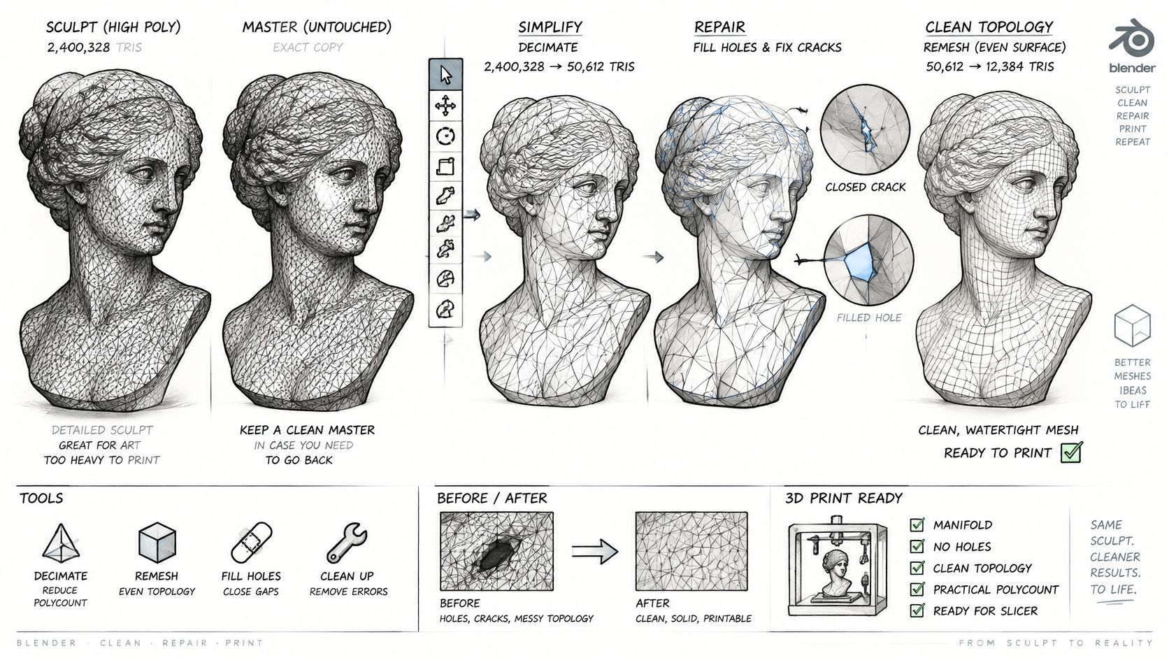
The repair workflow below is most useful for sculpts, imported scans, and AI-generated surfaces that look nearly printable but contain awkward intersections or unnecessary density.
Clean connectivity before reducing detail
- Merge only what should meet. In Edit Mode, select the relevant geometry and run Mesh → Clean Up → Merge by Distance. Start conservatively, because an excessive merge distance can fuse fingers, close engraved lettering, or collapse a narrow gap.
- Remove interior leftovers. Inspect Boolean joins and overlapping components in X-ray or wireframe view. Delete unwanted internal faces, and use a proper union when separate intersecting pieces must become a continuous body.
- Close intentional boundaries carefully. Fill a simple missing patch or use Bridge Edge Loops where corresponding boundaries should connect. Don't cap every opening indiscriminately, especially on hollow objects.
- Recalculate after connectivity changes. Select the repaired faces and use Recalculate Outside, then inspect Face Orientation again. Cleanup can expose orientation problems that weren't obvious beforehand.
For thin clothing, fins, or open surfaces, use Solidify or model an actual wall. Check the result around tight corners and narrow creases, because adding nominal thickness can produce self-intersections rather than a usable shell.
For FDM, choose wall thickness with the slicer's configured extrusion width in mind. Prefer walls that resolve into deliberate perimeter paths, and add material around loaded joints instead of relying on a universal minimum. A decorative cape and a load-bearing bracket need different judgments.
Choose the reduction tool by the defect
Use Voxel Remesh when an organic figurine needs a rebuilt, continuous surface. Choose a voxel size fine enough to preserve the smallest feature you intend to print, then inspect gaps between fingers, facial features, and the connection to the base. Coarse remeshing can make the shell cleaner while destroying the design.
Use Decimate → Collapse when the surface is already sound and the main problem is excessive geometry. Reduce gradually, comparing silhouettes and curved highlights rather than accepting the lowest triangle count that still resembles the object.
The Blender mesh simplification guide is useful when choosing between these reduction approaches. A game-ready quad layout is a separate deliverable; a slicer doesn't need animation-friendly edge loops.
Install or enable 3D Print Toolbox through the preferences workflow available in your Blender version. Run its checks for non-manifold geometry, intersections, and thickness, inspect the selected problem areas, and repeat after repairs.
Stop condition: The shell passes inspection, the dimensions remain correct, and further simplification would remove printable detail.
Decide Between the Print Mesh and the Master
Keep the master for changes. Export the print mesh for fabrication. That division lets you optimize a handoff without sacrificing the model you may need to pose, texture, resize, or rebuild later.
Choose binary STL when the recipient needs surface geometry for a slicer or compatible mesh-based CAD exchange. Don't assume importing it into a CAD application restores parametric features, design intent, or a clean editable solid.
The Blender STL documentation on import and export behavior distinguishes compact binary output, evaluated modifier export, and flat shading associated with imported facets. Those are useful manufacturing behaviors, but they don't make STL an archival substitute for a Blender project.
Choose the deliverable by the next task
| Next task | Keep or deliver |
|---|---|
| Revise modifiers, sculpting, or scene setup | Native .blend master |
| Transfer appearance or animation | A suitable GLB, FBX, or USDZ export, checked in the receiving application |
| Preserve an incoming generated asset | Original generator output, such as GLB or OBJ, plus the working project |
| Slice a validated print body | Separate binary STL |
| Revise a damaged print export | Return to the master and regenerate the handoff |
AI-generated meshes make this separation especially useful. A dense, irregular surface can become a satisfactory print after cleanup while remaining awkward to rig or edit. Conversely, retopology intended for animation can simplify away details you wanted on the physical object.
Keep the generator's original file before converting anything. Save the repaired print version separately so a later request for textured renders doesn't send you back to an appearance-free triangle mesh.
Finish with a receiving-tool check
File validation and printer selection are different decisions. If you're also evaluating machine capabilities and practical compromises, the H3c analysis from NeoTeo provides a separate resource to consult alongside your production requirements. Don't use hardware features as a reason to skip mesh inspection.
For the next handoff, export a size-labeled file, open that exact file in the intended slicer, and record its width, depth, and height. Then inspect the layers around the smallest connections before deciding on supports or infill. Keep the checked STL beside, not instead of, the editable source.
Sculpty offers browser-based AI model generation, remeshing, and exports including STL, GLB, and OBJ. Use it to create a source asset or prepare a mesh for Blender, then keep the richer original while you validate a separate STL for printing. Visit the studio to generate or import your next model and build a master-and-print workflow from the start.