
How to Model for 3D Printing: A Practical Workflow
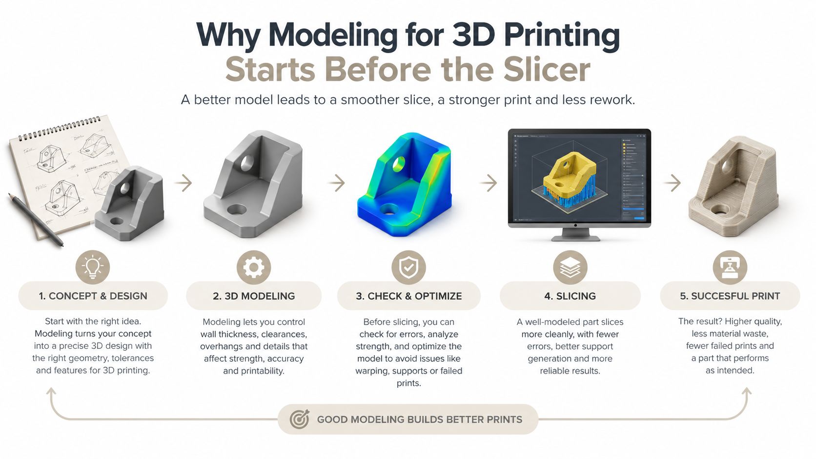
You've spent the evening adjusting support density, changing build angles, and re-slicing the same model, yet the print still fails in the same place. The usual culprit isn't a hidden slicer setting. It's often a wall that's too thin, a hole modeled at nominal CAD size, or a mesh that looked closed until the slicer had to interpret it layer by layer.
Learning how to model for 3D printing means making manufacturing decisions before the file reaches Cura, PrusaSlicer, Bambu Studio, or another slicer. Wall thickness, clearance, orientation, topology, and export format determine what the slicer has to work with. A good slicer can generate toolpaths for sound geometry, but it can't reliably rescue a design that was never printable.
Table of Contents
- Why Modeling for 3D Printing Starts Before the Slicer
- Designing Geometry Around the Print Process
- Building a Watertight, Manifold Mesh
- Hollowing, Supports, and Reducing Overhangs
- Choosing Between STL and 3MF for Export
- Verifying the Model Before You Hit Print
- Common Modeling Mistakes That Sink Prints
Why Modeling for 3D Printing Starts Before the Slicer
A thin-walled vase is a familiar trap. You can spend hours tuning tree supports around its rim, changing cooling settings, and trying different layer heights, but none of those adjustments repairs a wall that your FDM process can't form consistently. If the CAD model gives the printer too little material to deposit, support generation is treating the symptom rather than the cause.
The first decision is the process. FDM, resin, and powder-bed systems impose different limits on walls, holes, overhangs, and surface detail. Choose the process before committing to final geometry, then write a short print brief:
- Process: FDM, SLA, DLP, SLS, or MJF.
- Material: The material affects strength, shrinkage, flexibility, and surface behavior.
- Function: Decorative shell, enclosure, snap-fit part, threaded component, or moving assembly.
- Orientation: Which surfaces may show support scars, and which faces need dimensional accuracy?
- Post-processing: Decide whether sanding, curing, drilling, or assembly is acceptable.
That brief prevents a common mistake, designing a beautiful object first and asking the printer to solve its manufacturing problems afterward. For inspiration outside conventional digital modeling, it can also help to look at clay alternatives from 925 Studios, especially when the intended form is sculptural and the final object needs to preserve a handmade visual quality.
A practical workflow from brief to export
I use a sequence that keeps expensive decisions upstream:
- Select the process and define the part's purpose.
- Choose orientation before detailing the geometry.
- Build walls, holes, joints, and overhangs around process limits.
- Construct a closed, manifold volume.
- Decide whether hollowing and designed-in supports are appropriate.
- Export to STL or 3MF with units and object structure intact.
- Run a final inspection before opening the slicer.
This is also where the choice of slicing software becomes relevant. Your slicer controls toolpaths, supports, infill, and machine settings, but it doesn't replace CAD judgment. A practical overview of slicing software for 3D printing can help you match the downstream tool to the workflow you've already designed.
Practical rule: If a failure can be prevented by changing a vertex, face, wall, or clearance in CAD, fix it there. Don't outsource a design decision to an automatic slicer feature.
Designing Geometry Around the Print Process
A printable model isn't just a shape with a flat base. It's a shape whose dimensions account for how the printer deposits, cures, fuses, or binds material. The same part may work in resin and fail in FDM, or fit correctly in one process and bind in another.
Start with walls, not surface appearance
For FDM using a 0.4 mm nozzle, independent design guidance commonly treats about 0.8 mm as an absolute minimum wall, with 1.2 to 1.6 mm providing a safer general-purpose range and 2.4 to 3.2 mm being more appropriate for structural parts. Resin workflows can often use walls around 0.5 to 1.0 mm, depending on the material and geometry. These process-specific ranges are summarized in the 3D printing wall thickness guide.
Treat those figures as design boundaries, not guarantees. A tall unsupported wall, a flexible material, and a part that will be handled aggressively all need more consideration than a short decorative panel. Thickening every wall also isn't a universal fix. Excess material can trap resin or create internal stresses, so the section's function and manufacturing process matter together.
Set clearances for the way the part must move
Nominal CAD dimensions describe perfect geometry. Printed parts contain process variation, and assembled parts need room to move. For functional designs, reported overall tolerance bands are about ±0.15 to 0.30 mm for FDM/FFF, ±0.15 to 0.20 mm for SLA/DLP, and ±0.20 to 0.30 mm for SLS/MJF. Fit clearances may range from 0.00 to 0.15 mm for press fits through 0.40 to 0.70 mm for free-rotation fits, according to these 3D printing design guidelines.
Don't apply clearance as a decorative offset at the end. Decide whether the joint is meant to press together, slide, rotate, or remain loose, then place the clearance where the contact occurs. For a snap-fit, model the flexure, root radius, and insertion path as one system. A zero-clearance assembly may look precise in CAD and arrive as a fused block.
Choose orientation before committing to details
Use this decision tree:
- If a face must remain visually clean, orient it away from likely support contact.
- If a hole must stay round, avoid placing it across a layer direction that will distort its opening.
- If a joint must carry load, align the stronger material direction with the load where possible.
- If an overhang creates a large support scar, split, chamfer, or rotate the part before adding support geometry.
- If no orientation satisfies the functional and cosmetic requirements, redesign the assembly into printable components.
Overhangs beyond roughly 45 degrees from vertical often need support or a geometric change. Unsupported holes, underside ledges, and long horizontal spans deserve attention before export, not after the first failed layer. The most reliable designs use chamfers, arches, teardrop profiles, and split parts to reduce the amount of material printed into empty space.
Building a Watertight, Manifold Mesh
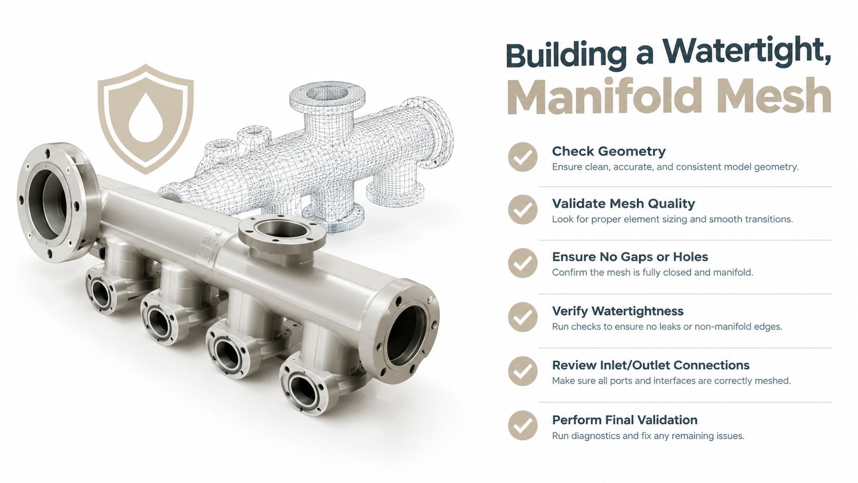
A slicer needs to identify the inside and outside of a solid. A manifold mesh gives it a clean boundary: every edge connects to exactly two polygons, and the model forms a closed volume. An open boundary, a duplicated face, or a non-manifold junction leaves the slicer to guess where material should exist.
A T-junction is a classic example. One surface terminates in the middle of another without creating a valid shared edge. Naked edges create holes, even if the gap is difficult to see in shaded view. Duplicate faces can overlap and create ambiguous surfaces, while boolean operations may leave tiny slivers or zero-thickness sheets inside the model.
The watertight mesh guidance from Hubs recommends checking the closed volume, inspecting normals, reviewing wall thickness, and exporting a slicer-friendly format. Those checks are more valuable than running an automatic repair and assuming the result is correct.
Build solids instead of surfaces
When modeling in CAD, prefer operations that produce a genuine solid body. If you work in a polygon package, cap openings deliberately and inspect every mirror seam. A surface shell can look complete while still lacking the volume information the slicer needs.
Normals matter too. Each face should point consistently outward. An inverted patch can be interpreted as an interior void or a reversed boundary, even when the shaded viewport looks normal. Face-culling or normal-display modes expose these errors quickly.
Triangulation also deserves attention. STL describes a model's surface as a triangular mesh, so curved forms need enough triangles to preserve their shape. A very coarse export produces visibly faceted cylinders and distorted arcs, while excessive density makes files harder to process without improving the physical result. Increase density around small details and curved transitions, then inspect the actual exported mesh instead of judging only the CAD preview.
A quick mesh inspection
Before slicing, import the exported file back into the CAD application or a mesh viewer and check:
- Closure: Look for gaps along seams, booleans, and mirrored joins.
- Normals: Switch to a face-orientation display and confirm consistent direction.
- Topology: Search for non-manifold edges, duplicate faces, and isolated shells.
- Scale: Compare a known dimension with the intended physical size.
- Detail: Zoom into holes, threads, embossed text, and thin ribs.
This short loop catches problems that a clean-looking modeling viewport can hide.
Hollowing, Supports, and Reducing Overhangs
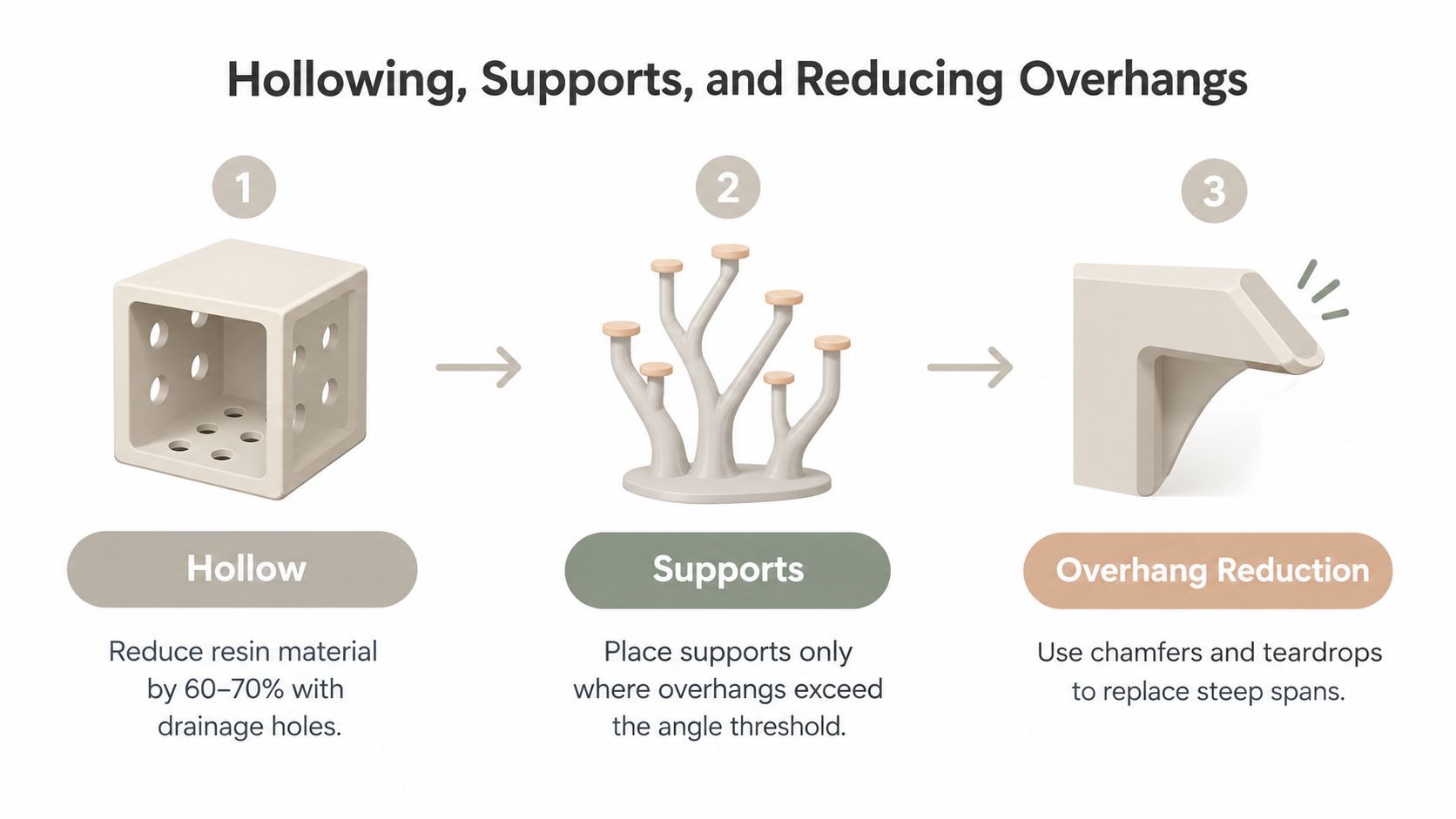
Hollowing is useful when a solid model contains a large enclosed volume, but it changes the engineering problem. You're no longer checking only the outside surface. You must also control the inner wall, drainage, trapped material, and the forces created during printing.
For FDM, hollowing can make sense when the part would otherwise require more material than its function needs. For resin, it's especially important to provide a path for uncured resin to leave the cavity. A sealed hollow print can trap liquid inside, add weight, and create pressure during the print.
Hollow deliberately
Choose the inner wall according to the process, material, and handling needs. The wall thickness guidance for 3D printing is a useful reference for comparing process-specific limits, but the model still needs a visual and mechanical review.
Place drainage and escape holes where liquid can flow out during the chosen orientation. Opposite sides of a cavity often drain more predictably than a single opening, especially when internal geometry creates pockets. Avoid placing holes directly under delicate edges or in areas that must remain watertight after curing.
A hollow model also needs internal transitions that don't create knife edges. Round internal corners where possible, and inspect the cavity in section view. The external silhouette may be perfect while the inner shell intersects itself.
Redesign beats automatic support generation
Support is sometimes necessary, but it shouldn't be the first response to every overhang. Try these changes in CAD:
- Chamfer an underside: Replace a sharp step with a sloped transition.
- Use a teardrop opening: This preserves a round functional passage while keeping the roof printable.
- Split the assembly: Separate a body into pieces that can each rest on a stable face.
- Change thread orientation: A vertical thread may need less support and clean more reliably than a horizontal one.
- Add a controlled contact: If support is unavoidable at a critical surface, design a sacrificial pad or breakaway feature.
The familiar 45-degree overhang threshold is a useful starting point, but small features, cooling, layer height, and material can shift the practical result. Test the geometry with a small sample before committing to a large part.
Choosing Between STL and 3MF for Export
STL remains the dependable handoff format because nearly every slicer understands it. It represents the model surface as triangles, but it doesn't carry the broader project context that modern multi-object and multi-material workflows often need. The format was developed by 3D Systems in 1987, documented in the StereoLithography Interface Specification in 1988, and became a de facto rapid-prototyping standard in the 1990s, as described in this overview of the STL file format).
3MF is often more useful when a file must preserve relationships between multiple bodies, materials, colors, or print settings. The choice depends on where the file is going next and how much information the receiving tool must understand.
| Feature | STL | 3MF |
|---|---|---|
| Geometry | Triangular surface mesh | Geometry in a structured package |
| Multiple objects | Usually handled as separate or loosely grouped meshes | Can preserve multiple objects in one project |
| Color and material context | Limited in ordinary STL workflows | Better suited to carrying project metadata |
| Workflow simplicity | Widely supported and easy to open | More useful for richer print projects |
| Best fit | Single-part or single-material handoff | Multi-object, multi-material, or tool-to-tool workflows |
Binary STL still has a place
For a single-color FDM part, binary STL is often the least complicated route. It processes faster and is smaller than ASCII STL, while retaining the same basic surface description. ASCII STL can be useful for inspection in a text editor, but it adds no manufacturing intelligence and can become unnecessarily heavy.
Units deserve a deliberate check. STL workflows have historically been vulnerable to unit ambiguity, so compare a known model dimension after import. If the part arrives at an unexpected size, fix the export settings or scale at the source rather than hoping the slicer guessed correctly.
Use 3MF when context matters
Choose 3MF when the recipient needs more than one anonymous triangle mesh. It's a sensible option for assemblies, color-separated objects, or a project moving through several compatible tools. Still, open the exported file before sending it onward. Confirm that objects remain separate, the scale is correct, and the receiving application recognizes the geometry as expected.
For a focused explanation of the older format's role and limitations, see this guide to STL files for 3D printing. The practical rule is simple: use STL for straightforward compatibility, and choose 3MF when preserving project structure reduces ambiguity.
Verifying the Model Before You Hit Print
The final check should be boring. That's a good sign. A repeatable inspection catches CAD errors before they become wasted material, lost print time, or a part that fails only after several hours.
Start with four questions:
- Is the mesh manifold? Every edge should belong to exactly two faces.
- Are the normals consistent? An inverted patch can create a hole or reversed region.
- Is the scale correct? Verify a known dimension after export and import.
- Are the walls and openings appropriate? Measure the areas most likely to break, fuse, or deform.
Free mesh viewers can identify open boundaries and non-manifold edges, while many CAD packages provide solid validation and thickness analysis. Don't rely on the slicer's automatic repair as your only inspection. A repair tool may close a hole, but it can also alter an edge, fill an intended opening, or create a surface you didn't design.
Inspect the file you will actually print
Export first, then inspect that exported file. The source CAD body may be valid while the tessellated mesh contains a seam, an unexpected shell, or insufficient resolution around a curved feature.
Use a section view or clipping plane to inspect hollow parts and internal intersections. Rotate the model under flat shading rather than relying only on glossy surfaces. Look for dark patches, missing faces, pinched triangles, and edges that disappear when the lighting changes.

A browser-based STL viewer can be convenient for a quick visual pass, particularly when you're checking a file on a machine without your full CAD installation. Remeshing and retopology tools can help when an imported or generated asset has irregular topology, but they shouldn't replace decisions about functional walls, fit, and orientation.
Make the audit habitual
Before sending the file to the slicer, confirm:
- The model sits at the intended origin and doesn't contain a hidden offset.
- The unit and physical scale match the print brief.
- Critical holes, slots, and mating faces have process-appropriate clearance.
- Thin ribs, tabs, and embossed details have enough material to survive handling.
- The selected orientation doesn't create an avoidable support scar or weak joint.
- The exported file opens cleanly in the target slicer.
The inspection takes little time once it becomes routine. It keeps you from confusing a CAD problem with a printer problem.
Common Modeling Mistakes That Sink Prints
“The slicer will fix it” is a dangerous assumption. A slicer can sometimes repair a simple hole or generate a usable path around a minor defect, but it can't know whether a thin wall is intentional, whether two parts should move freely, or whether an inverted face represents a cavity.
Geometry errors
The first category begins with dimensions. Walls below the process limit may disappear, become fragile, or fail to adhere. Holes modeled at nominal size can print undersized, and assemblies with zero clearance often fuse together.
Fix these problems at the feature level. Increase the wall where it carries load, enlarge the opening where a fastener or pin must pass, and define clearance between the actual contact surfaces. Don't scale the entire model to compensate for one undersized hole.
Overhangs create a second geometry failure. A designer may preserve a sharp underside because it looks elegant in CAD, then discover that the printer needs support across the entire span. A chamfer, radius, arch, or split line usually produces a cleaner result than a dense forest of support columns.
Topology errors
Open meshes, inverted normals, duplicate faces, and zero-thickness geometry often come from boolean operations, mirrored parts, or deleted construction surfaces. The model can appear fine in solid shading while the slicer sees several competing shells.
Run a mesh validation pass after major operations, not only at the end. If you've mirrored half a part, inspect the seam. If you've cut a cavity, check the interior walls. If you've joined separate bodies, confirm that the result is one intended volume rather than overlapping shells.
Export errors
Export can introduce its own confusion. Unit interpretation may change between applications, object transforms may remain unapplied, and a file can contain several bodies when the receiving workflow expects one. The remedy is a round trip: export, reopen, measure, and compare with the source.
Use this short pre-export audit:
- Confirm minimum wall and feature dimensions for the selected process.
- Run a manifold and boundary check.
- Display normals and correct reversed faces.
- Verify units and one known physical measurement.
- Check origin, orientation, and object separation.
- Reopen the final STL or 3MF in the intended slicer.
Treat the audit as part of modeling, not administrative cleanup. The reliable print usually starts with a model that has already answered the slicer's most important questions.
Sculpty provides a browser-based workflow for generating, remeshing, retopologizing, viewing, and exporting 3D assets in formats including STL and 3MF. If you want to move from an idea or reference image to a mesh you can inspect against these printability rules, visit Sculpty and review the model before sending it to your slicer.