
Fixing Non Manifold Geometry in Blender
You've finished a model in Blender. The silhouette looks right, the surface shading looks smooth, and the export completes without a warning. Then your slicer drops a wall, a Boolean leaves fragments behind, or a collision mesh behaves strangely. The visible shape isn't necessarily the problem. The connections between its faces may be.
Fixing non manifold geometry starts with identifying those connections, not clicking every cleanup command available. A reliable repair preserves the object you intended to make, then verifies that the next tool can use it.
Table of Contents
- What Non-Manifold Geometry Means in Plain Terms
- Real Examples Where Non-Manifold Geometry Appears
- Why Non-Manifold Geometry Breaks Prints, Games and AI Meshes
- How to Detect Non-Manifold Edges and Vertices
- When Automatic Repair Makes Things Worse
- Repair Non-Manifold Geometry Step by Step
- Prevent Non-Manifold Geometry While Modeling
- Confirm the Mesh Is Ready Before You Export
What Non-Manifold Geometry Means in Plain Terms
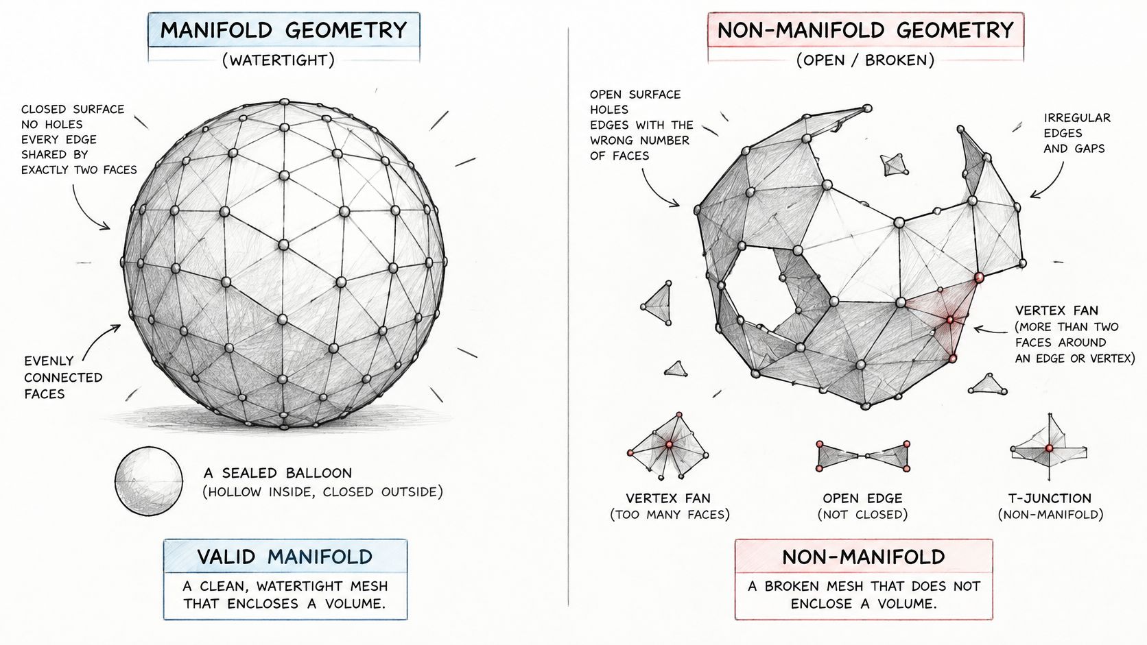
Think of a sealed balloon as a simple manifold surface: every small patch belongs to one continuous skin. Attach another sheet along a seam so that several surfaces branch from the same edge, and that seam becomes non-manifold.
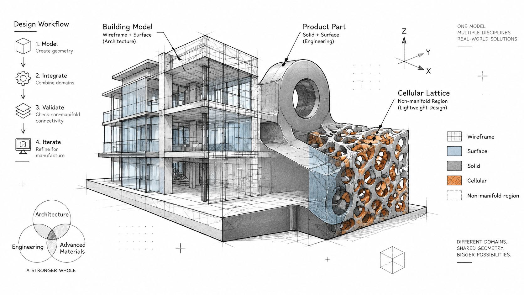
For an ordinary polygon surface, each interior edge belongs to exactly two faces, and the faces around each vertex form one continuous fan. Non-manifold representations relax those conditions, allowing branching surfaces or combinations of surfaces, solids, and wires. The CAD/CAE study on unified non-manifold modeling_2004_585-594.pdf) describes a data structure that accommodates wireframe, surface, solid, and cellular models together.
Manifold doesn't automatically mean closed. An open sheet can be a valid manifold surface with a boundary, although it isn't a watertight solid. Blender's non-manifold selection includes boundaries because they matter in many solid-model workflows.
Non-manifold conditions and their effects
Some common cleanup problems are strictly topological. Others, such as duplicate faces, are related validity defects that deserve separate checks.
| Condition | What it looks like | Valid manifold rule | Typical effect |
|---|---|---|---|
| Edge shared by three or more faces | Three walls meet at one seam | Each interior edge touches exactly two faces | Slicer may not distinguish inside from outside |
| Open boundary edge | A hole in an otherwise closed shell | A closed triangulated shell requires two incident triangles per edge | Missing walls or unintended infill |
| Pinched vertex | Two cubes touching at a single corner | Each vertex has one continuous face fan | Ambiguous adjacency for subdivision, UVs, and retopology |
| Internal face inside a solid | A wall hidden inside the volume | A simple solid's boundary separates material from empty space | Unexpected cavities or incorrect material regions |
| Wire edge with no face | A stray line left in the mesh | Every edge in a surface mesh bounds at least one face | Edge may be ignored or rejected downstream |
| Duplicate or zero-area face | Identical triangles or a collapsed sliver | Faces should be unique and have nonzero area | Z-fighting, failed Booleans, or slicer errors |
Read the table as a diagnostic guide, not a declaration that every listed structure is always forbidden. An internal partition may be intentional in an engineering model, while a floating face inside a printable figurine usually isn't.
Practical rule: Check edge face counts and vertex fan connectivity before trusting the shaded viewport.
Those checks reveal connectivity that a smooth material can hide. Non-manifold structure can be useful in CAD and simulation, but printing and game-production tools need geometry that matches their particular assumptions.
Real Examples Where Non-Manifold Geometry Appears
Say you're preparing a building model for energy analysis. A room isn't just empty space inside an exterior shell. It's a meaningful region with boundaries shared by neighboring rooms, corridors, and outdoor space.
A 2022 study on generative design for additive manufacturing describes non-manifold representations for connected beam, shell, and solid regions, alongside cellular models that distinguish solid, fluid, and void regions. It also discusses architectural energy-modeling applications with matched surfaces and medical modeling involving complex internal zones.
When shared boundaries carry information
In a building model, a shared interface can describe heat transfer between adjacent zones. Removing it merely to produce a single exterior skin would discard information the analysis needs.
A medical model may likewise preserve distinct internal regions rather than flatten everything into an outer envelope. A generative engineering model can connect beam-like supports to shell-like panels and solid mounting regions without pretending they're all the same kind of element.
The topology expresses relationships, not just appearance.
An internal partition makes sense in a house plan. A branching sheet in the skin of a boat hull is a different matter: the receiving workflow needs an unambiguous enclosure, not a network of spatial regions.
When the structure is accidental
Modeling leftovers can create similar connectivity without serving any purpose. An extrusion canceled after geometry was created, an unfinished Boolean, or overlapping imported shells can leave hidden components behind.
Scanned and AI-generated assets also need inspection rather than an assumption of cleanliness. The authors of Simplifying Textured Triangle Meshes in the Wild reported in 2024 that approximately 98.9% of ShapeNet meshes are non-manifold. That finding describes ShapeNet meshes, not a universal failure rate for every generator or asset library.
For an imported character, inspect separate shells before welding them together. An eyeball, clothing layer, or accessory may be a legitimate separate component.
The useful question is whether the structure belongs there for the next tool in the pipeline. Repair decisions become much clearer once you know what each region represents.
Why Non-Manifold Geometry Breaks Prints, Games and AI Meshes
A successful STL export proves that triangles were written, not that a usable solid was created. The STL limitations guide explains that STL lacks reliable topology and error-checking constraints, leaving importers, repair tools, and slicers to establish validity.
A viewport can display triangles without resolving which side contains material. A slicer, collision system, or modeling operation may need a much more definite answer.
Pipeline failures caused by non-manifold topology
| Pipeline | Typical failure | Why the topology causes it | Check before handoff |
|---|---|---|---|
| 3D printing from STL | Missing walls, odd infill, rejected job | Slicer cannot derive an unambiguous solid volume | Confirm a closed, consistently oriented shell at print scale |
| Game engines such as Unity and Unreal | Bad collision, light leaks, shading seams | Ambiguous surfaces and normals can conflict with collision or rendering assumptions | Check normals and inspect hidden interior faces |
| Simulation and finite-element analysis | Wrong results or failed solver setup | Unexpected connectivity can invalidate the solver's model assumptions | Verify connected bodies and required interfaces |
| Boolean and modeling operations | Failed unions, cuts, leftover slivers | Solid Booleans need coherent intersecting volumes | Check topology and intersections before the operation |
| AI-generated meshes | Internal shells, thin appendages, overlapping parts | A plausible preview can conceal disconnected or overlapping geometry | Inspect and separate shells before retopology |
What those failures look like
Consider a printable figurine with an accidental internal face joining its outer shell. The slicer may omit part of a wall or interpret a region as an unexpected cavity. Inspecting the toolpath is more useful than checking whether the figurine still looks attractive in solid shading.
For a game asset, a pinched connection can complicate smoothing and collision preparation. A visible lighting seam might also come from split normals or UVs, so don't diagnose every shading artifact as non-manifold geometry.
Simulation requires equal care. A solver may reject invalid connectivity, but it may also process a model whose regions no longer represent the intended physical system. A completed calculation isn't proof that the model was appropriate.
A mesh can be renderable without being suitable for collision, subdivision, fabrication, or analysis.
With AI-generated assets, inspect thin appendages and intersecting accessories particularly closely. Don't delete a hidden shell just because it's hidden; determine whether it represents a separate part first.
Clean connectivity gives downstream tools a clearer basis for classifying surfaces and regions. Combined with intersection checks and correct orientation, it supports more predictable Booleans, subdivision, and retopology.
How to Detect Non-Manifold Edges and Vertices
Start with edge face counts, inspect unexpected boundaries, and then check pinched vertices. Follow those with duplicate-face, degenerate-face, and self-intersection checks. This order helps distinguish a branching seam from several unrelated defects occupying the same location.
Find the selection in Blender
Enter Edit Mode, deselect everything, switch to vertex selection, and choose Select > All by Trait > Non Manifold. Open the operator options to inspect Wire, Boundaries, Multiple Faces, Non Contiguous, and Vertices individually.
Toggle categories rather than accepting one crowded selection. If only Boundaries highlights geometry, you're investigating an open surface, not necessarily a branching edge. Use X-ray or wireframe view to inspect selected components hidden behind the exterior.
| Tool | Check or menu path | What it reports |
|---|---|---|
| Blender | Select > All by Trait > Non Manifold | Selects wire edges, boundaries, multiple-face edges, non-contiguous connections, and non-manifold vertices |
| Blender 3D-Print Toolbox add-on | 3D-Print panel > Check All | Lists solid/manifold problems, thin regions, and intersections |
| MeshLab | Filters > Quality Measure and Computations > Topological Measures | Reports topology measures including boundaries, non-manifold elements, and genus |
| MeshLab | Filters > Cleaning and Repairing > Remove Duplicate Faces and Remove Zero Area Faces | Removes duplicate triangles and degenerate faces before reassessment |
| CGAL, scripted use | is_non_manifold_vertex() |
Flags non-manifold vertices for automated checks |
Menu wording and extension availability can differ by application version. Install or enable Blender's 3D-Print Toolbox if its panel isn't available, then use Check All for a broader overview than the selection command alone.
Understand the vertex umbrella
Mentally walk from face to neighboring face around a vertex. For a normal interior surface vertex, that traversal should cover one connected fan.
The CGAL polygon mesh repair documentation calls attention to disconnected vertex umbrellas and provides is_non_manifold_vertex() and duplicate_non_manifold_vertices(). Splitting a shared vertex restores separate combinatorial sheets, but the new vertices retain identical coordinates, so the surfaces may still touch or intersect geometrically.
That distinction matters when two cubes meet at a corner. Separating their vertex records doesn't move the cubes apart.
In MeshLab, remove duplicate and zero-area faces before measuring again, since these can distort the diagnosis. Compare defect counts after each operation, but don't interpret every reported value as something that must reach zero: genus, connected-component counts, and intentional boundaries describe structure, not automatically errors.
A clean topology report still needs a geometric intersection check.
When Automatic Repair Makes Things Worse
Make manifold isn't a universal repair button. A tool can produce cleaner adjacency while deleting a feature, sealing a functional opening, or joining parts that were supposed to move independently.
A mesh-manifold requirements document provides a useful reference for local mesh validity. Treat that validity as a starting condition, not a manufacturing certificate.
Validate separate layers in order
- Topological validity. Check face adjacency, vertex fans, duplicates, and degenerate elements.
- Watertightness. Where a solid is required, verify complete enclosure and coherent orientation.
- Manufacturability. Measure wall thickness, clearances, and fragile features at the intended physical size.
- Slicer-specific behavior. Inspect the actual generated paths with the intended settings.
Use this checklist before accepting an automatic repair.
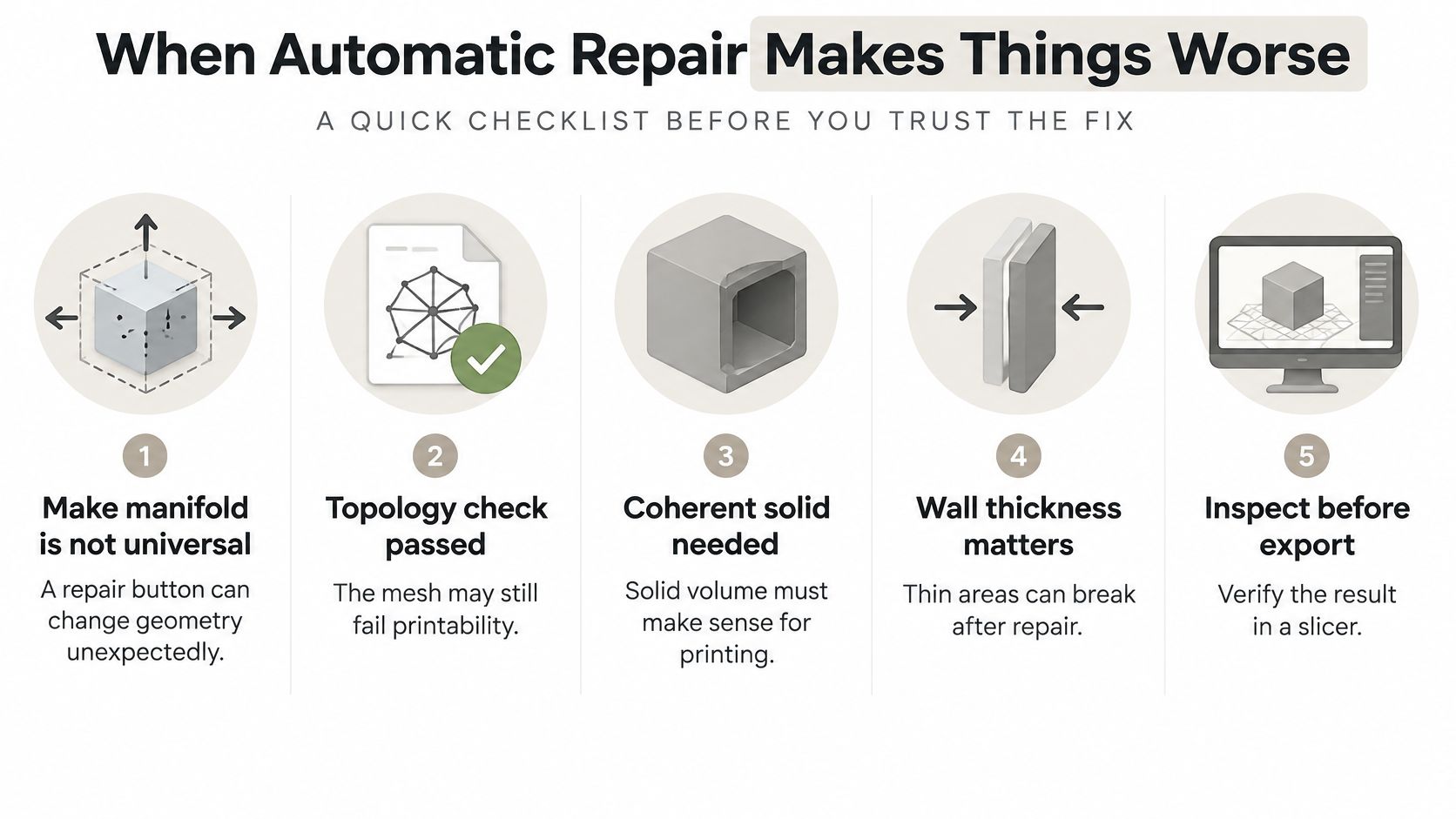
A repair that retains only a valid pair of faces at a branching edge may discard a thin appendage. A global hole-fill operation may cap a drainage passage instead of rebuilding its missing inner wall.
Likewise, merging nearby shells can eliminate assembly clearance. Smoothing can reduce thickness even when the result remains topologically valid, and inconsistent normals can leave a closed surface oriented incorrectly.
Preserve intent: Repair one defect type at a time, keep the original file, and inspect the result after each change.
If cleanup also involves reducing polygon density, use a controlled Blender mesh simplification workflow rather than combining aggressive simplification with unreviewed repair. Otherwise, you won't know which operation changed the silhouette or erased a gap.
A repair is correct only when it resolves the unwanted connection without sacrificing intended geometry. Passing a checkbox isn't enough.
Repair Non-Manifold Geometry Step by Step
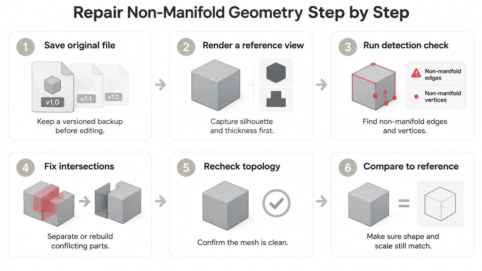
Save a versioned copy before editing, then capture a reference view showing the silhouette and delicate features. Record the object's dimensions too, because a matching camera view won't reveal every scale or thickness change.
Use the workflow below as a sequence of small, reversible passes.
Make targeted changes
- Record the starting defects. Run detection and note unexpected boundaries, branching edges, pinched vertices, and duplicate faces. Keep intentional components separate in your notes.
- Remove duplicates and degenerates. Delete duplicate faces and collapsed polygons before judging the remaining connectivity.
- Merge only duplicate vertices. In Blender, use Merge by Distance with a threshold appropriate to the model's units. Preview the result around narrow gaps and fine details.
- Inspect loose parts individually. Use Separate > By Loose Parts where helpful. Examine a section cut before removing an internal shell; it may represent a functional component.
- Resolve pinched connections. Split sheets that should remain separate. Re-weld only where you intend a continuous surface.
- Rebuild openings and overlaps deliberately. Fill accidental gaps. For a vent or drain, preserve the passage while constructing a closed rim and inner wall where a printable solid requires them. Union overlapping shells only when they should become one body.
- Reconstruct severely damaged surfaces. Remesh when local repair becomes impractical, then retopologize for the intended use. Compare thin features, openings, and silhouette against the reference.
- Recheck after every pass. Finish with orientation, intersection, section-view, and slicer checks. Stop only when unintended defects are resolved.
Defect, first fix and verification
| Defect | First fix | Tool | Verify after |
|---|---|---|---|
| Duplicate vertices at one location | Merge with a small distance threshold | Blender Merge by Distance | Intended seams join without collapsing gaps |
| Pinched vertex with several fans | Split sheets, re-weld only intended joins | Blender Rip Vertices or CGAL duplicate_non_manifold_vertices() |
Sheets no longer share unintended connectivity or intersections |
| Internal faces or hidden inner shell | Remove only confirmed unwanted geometry | Blender Select Interior Faces, followed by manual inspection | Section cut shows the intended material regions |
| Deliberate opening such as a vent | Preserve passage; retain an open boundary only for an intentionally open surface | Manual rim and inner-wall modeling | Slicer preserves the passage |
| Accidental open boundary | Fill or rebuild the missing patch | Blender Fill Holes or MeshLab Close Holes | Unexpected boundary disappears |
| Overlapping shells meant to form one solid | Boolean union | Blender Boolean Union | No unwanted internal interface remains |
| Badly broken AI-generated mesh | Remesh, then retopologize | Sculpty remesh and retopology | Reference shape is preserved and validation passes |
For a visual demonstration, inspect the mesh selections alongside your own model rather than applying every operation indiscriminately.
Prevent Non-Manifold Geometry While Modeling
Keep parts that are meant to remain separate as separate objects. Don't rely on a single shared corner to connect a handle, accessory, or mechanical component.
After extrusions, deletes, and mirror operations, inspect the affected area before adding more detail. Canceled movements can leave newly created geometry behind, while overlapping pasted geometry can conceal duplicate faces.
Build checks into modeling milestones
- Inspect Boolean results immediately. Use Select > All by Trait > Non Manifold before continuing to sculpt or subdivide.
- Keep cavities explicit. Model their inner walls and rims instead of placing unexplained faces inside a volume.
- Review imports before editing. Identify clothing, accessories, scan fragments, and nested shells before welding anything.
- Name functional components. Label inserts, liners, and separate moving parts so later cleanup doesn't remove them.
Good 3D modeling topology habits make defects easier to trace. If you validate at meaningful milestones, you can usually identify the operation that introduced a problem rather than reconstructing the history of an entire finished asset.
Keep a known-good version before destructive operations. Prevention is easiest when undoing one change is still practical.
Confirm the Mesh Is Ready Before You Export
Approve the asset for its destination, not merely for its appearance. A printable enclosure, an open game environment, and a simulation model don't share identical acceptance criteria.
Use the ordered validation layers as a handoff checklist:
- Topology passes. No unintended branching edges, pinched vertices, duplicate faces, or degenerate polygons remain.
- Enclosure matches the task. Required solids are closed and consistently oriented; separate shells have documented purposes.
- Physical dimensions work. Measure walls and clearances at actual print size, and test critical features when necessary.
- The receiving tool agrees. Re-slice at the intended layer height and inspect walls, cavities, passages, and transitions.
For physical production, follow a modeling-for-3D-printing workflow rather than judging thickness in an unscaled viewport. Keep the final validation notes with the saved original.
Export STL or 3MF for compatible slicers, or choose GLB, OBJ, or FBX according to the requirements of your game engine or editing application. Reopen the exported file when the handoff matters, because export settings can change what reaches the next tool.
Run that final receiving-tool check before committing to a print or delivery.
Sculpty offers browser-based remeshing and retopology alongside AI-assisted 3D creation. Visit Sculpty to prepare a difficult mesh for cleanup, then validate the result in Blender and your destination tool before export.