
Different Views of 3D Objects: A Practical Guide
Using 4, 6, 8, or more views often improves recognition, while 20 views has enabled state-of-the-art performance in several multi-view methods. The right number still depends on the job, because a view for modeling isn't the same as a view for printing, presentation, or web interaction.
You're staring at a finished 3D object, a deadline is approaching, and someone asks for “the right view” without explaining what they need. Should you send the front, an attractive three-quarter render, a top view, or a complete rotation?
The answer starts with purpose. Different views of 3D objects are the same mesh seen from different camera positions and flattened according to different projection rules. One view can expose the silhouette, another can reveal hidden geometry, and another can make the object feel convincingly present in a scene.
A single image often hides the information your audience needs. The toolkit below connects each view type to a downstream job, including modeling, 3D printing, technical documentation, presentation, rendering, and interactive web display.
Table of Contents
- When One Picture of a 3D Object Is Not Enough
- How Cameras and Projections Actually Work
- Orthographic Views for Building and Printing
- Perspective and Isometric Views for Presentation
- Turntable and 360-Degree Views for the Web
- Matching the Right View to the Right Job
- Why More Views Are Not Always the Answer
When One Picture of a 3D Object Is Not Enough
A client reviewing a chair model may approve the front image while missing a clipped rear leg. A product designer may like the hero render while failing to notice that the lid is too shallow. A printer may receive a beautiful perspective image that says almost nothing about support placement or the object's true footprint.
One screenshot fails for three practical reasons:
- Hidden surfaces: The camera shows only the visible side, so the back, underside, and areas behind overlaps remain uncertain.
- Scale distortion: Perspective makes nearby parts appear larger and distant parts smaller, which is useful for realism but unreliable for measurement.
- Unclear proportions: A dramatic angle can make a thin wall look thick, or a short object look deep, depending on the camera position and lens.
Practical rule: Choose the view by asking what decision the viewer must make, not by asking which angle looks most attractive.
A view is a communication tool. A front orthographic view helps you align a character's eyes and shoulders. A side view exposes the depth of a helmet. A top view confirms whether a printed enclosure fits its intended footprint. A perspective render helps a buyer understand mood, material, and scale.
The history of reconstruction reflects the same shift from isolated images toward multiple observations. Photometric stereo appeared in 1977, and a landmark uncalibrated 3D method followed in 1998, two important steps toward recovering shape from more than one image. The field later developed from classical multi-view geometry into neural reconstruction methods that use varied viewpoints to build detailed models. This history of 3D reconstruction provides useful context for why camera coverage matters.
How Cameras and Projections Actually Work
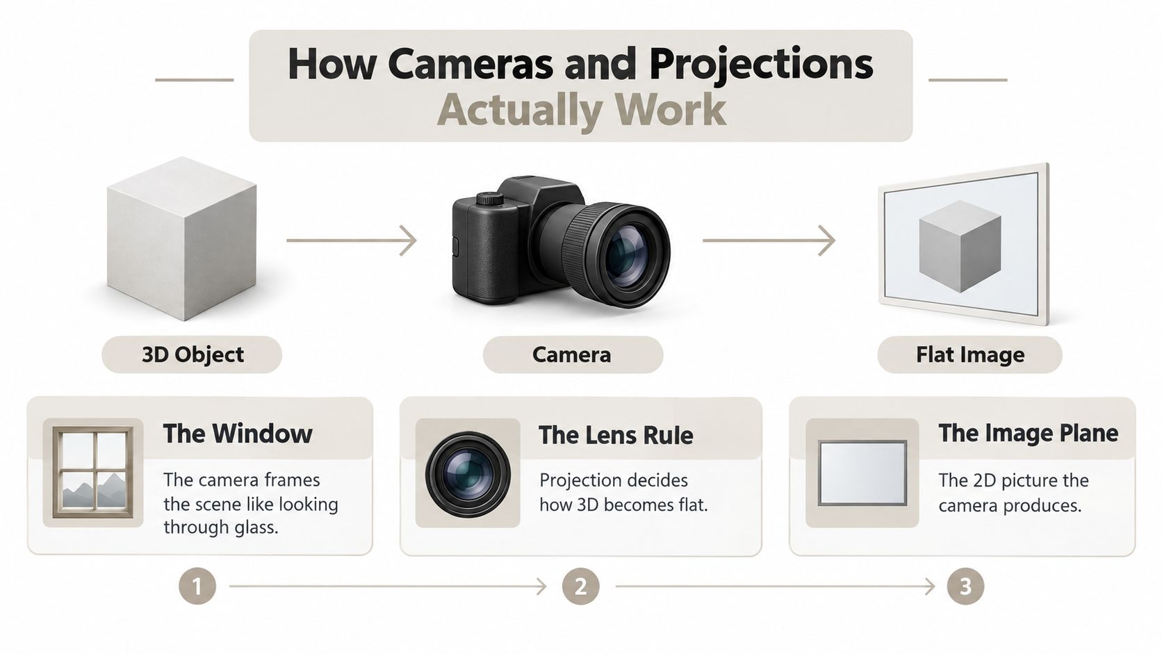
Think of a virtual camera as a window and projection as the rule governing what reaches the glass. The object exists in three-dimensional space, the camera frames part of that space, and the projection turns the framed scene into a flat image.
That simple model explains most view choices.
Orthographic projection keeps projection lines parallel. A point farther from the camera doesn't shrink just because it is farther away, so the image preserves a more reliable sense of width and height. This makes orthographic views useful for technical drawings, alignment, measurement, and reference images.
Perspective projection behaves more like human vision. Lines that are parallel in the actual world can appear to converge toward vanishing points, and distant parts look smaller. That apparent distortion is valuable in a render because it creates depth and gives the viewer a familiar visual experience.
The camera orbit
Keep the object still in your mind. The camera moves around it, changes height, changes distance, or changes its lens angle. Each adjustment changes which faces appear, how much of each face is visible, and how strongly depth is represented.
A low camera can make a model feel imposing. A high camera can reveal the top surface and clarify the layout of components. Moving the camera farther away and adjusting the lens can produce a calmer composition than standing close with a wide lens.
For a deeper look at how several angles support reconstruction, see this guide to multi-view 3D reconstruction.
Orthographic cameras usually orbit in fixed right-angle steps for a familiar engineering set: front, side, top, and sometimes rear and bottom. Perspective cameras are more flexible because they're usually chosen for visual impact rather than strict measurement.
Orthographic Views for Building and Printing
When you're modeling, orthographic views act like a transparent reference grid around the object. The front view shows height and width. The side view shows height and depth. The top view shows width and depth. Together, they describe the main proportions without allowing perspective to disguise errors.
Suppose you're blocking out a stylized robot. In the front view, you align the shoulders, feet, and antenna along the vertical axis. In the side view, you discover that the chest projects too far forward. In the top view, you notice that one arm sits closer to the torso than the other. A perspective viewport might make these mistakes look acceptable because depth and lens effects soften the comparison.
Use the view that matches the axis
In Blender, Maya, and ZBrush, switching to an orthographic front, side, or top view gives you a stable way to move vertices along known axes. You can compare a silhouette against a drawing, line up mirrored components, and check whether a circular opening remains centered.
Technical illustrators use the same view family for dimensioned drawings because the image doesn't intentionally shrink distant features. A width read from the front view should agree with the corresponding width represented in another aligned view. Orthographic projection doesn't make the object look cinematic, but it gives the viewer a dependable description.
For 3D printing, this distinction becomes practical. A slicer workflow needs you to inspect the model's orientation, contact with the build plate, overhangs, cavities, and likely support regions. A front or side orthographic view exposes the vertical profile, while a top view reveals the footprint and whether important openings are blocked.
A production check
Before exporting a printable STL or 3MF, inspect at least these views:
- Front: Check the main silhouette, height, and visible overhangs.
- Side: Check depth, lean, wall thickness relationships, and hidden projections.
- Top: Check the footprint, openings, symmetry, and build-plate placement.
- Bottom or rear: Add this when the underside or back contains functional geometry.
Use orthographic views whenever accuracy, alignment, or measurement matters more than realism. If the viewer must decide whether parts line up or whether a form fits, don't send only a perspective render.
Perspective and Isometric Views for Presentation
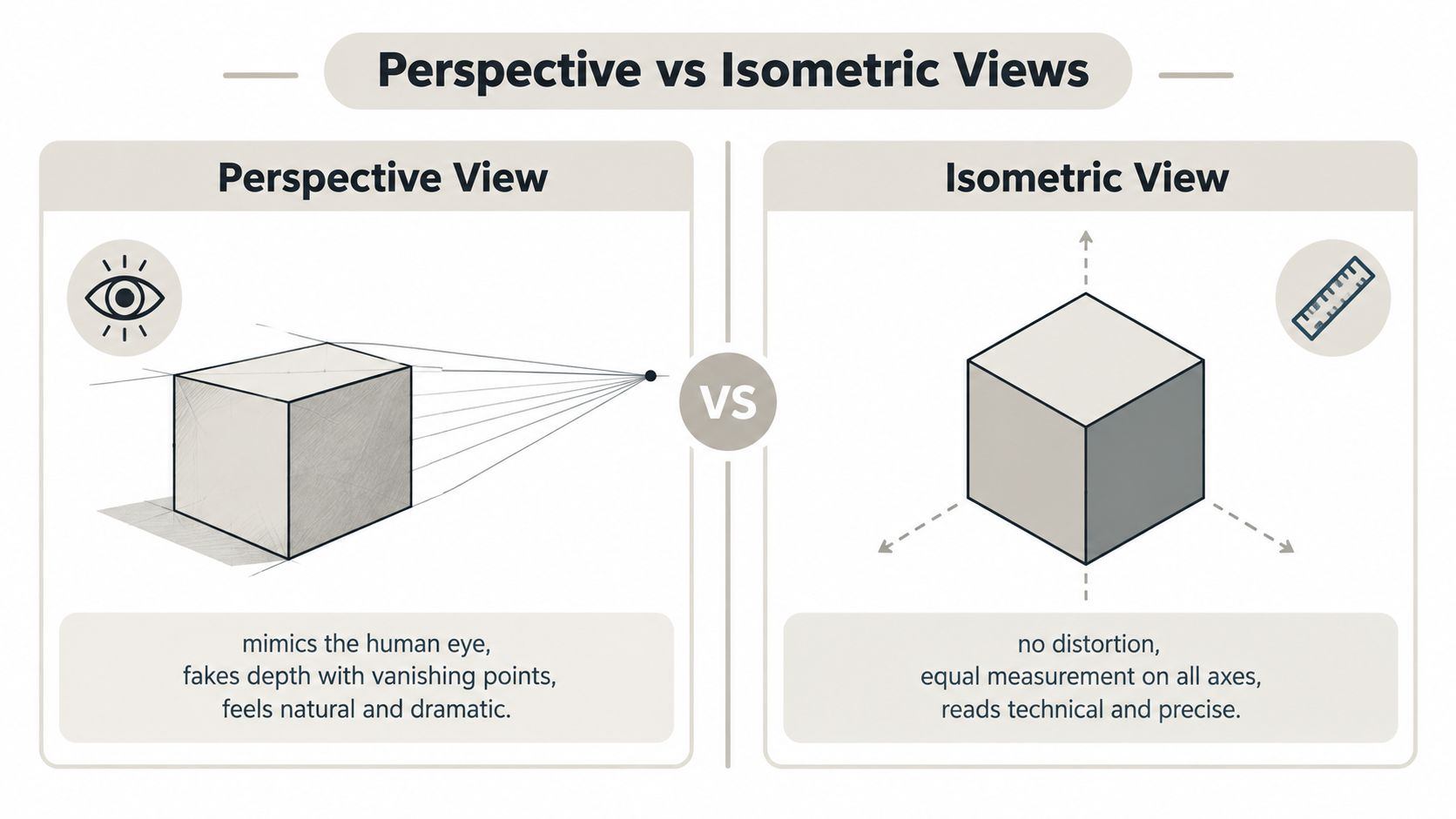
Perspective and isometric views speak different visual languages. Perspective says, “This is how the object might feel in the world.” Isometric says, “This is how the parts relate to one another without visual favoritism.”
Perspective projection uses convergence and scale change to create depth. Product photographers, architectural visualizers, and marketing artists use it because viewers recognize the result immediately. A nearby edge feels larger, a distant surface recedes, and the composition can direct attention toward a hero feature.
Isometric projection keeps parallel lines parallel and gives the major axes balanced visual weight. It works well for technical illustrations, game interface icons, assembly diagrams, and exploded views where the audience needs to compare components rather than feel cinematic scale.
Pick the language before the camera
Choose perspective when the audience needs atmosphere, physical presence, or a sense of scale. A product hero image, a room interior, or a cinematic game asset benefits from controlled foreshortening and a believable relationship between near and far surfaces.
Choose isometric when the audience needs clarity at a glance. A UI icon for a building game, a warehouse layout, or an exploded mechanical diagram often becomes easier to read when the axes stay visually consistent.
For a practical overview of viewing assets in the browser, this online 3D model viewer guide can help you think about how users inspect an object after the still image is delivered.
Medical and scientific imagery adds another reason to favor controlled, readable views. If you're preparing a diagram or asset for clinical communication, a resource on MyImageUpscaler for medical imaging offers context for improving image presentation without turning a technical view into a decorative one.
Common mistakes come from choosing a view for the wrong audience. Perspective can mislead when you're trying to compare tileable game-art assets. Isometric can feel lifeless when a film frame needs drama and spatial immersion.
Audience test: If the viewer should feel the object, use perspective. If the viewer should compare the object, use isometric.
The next practical question is what happens when a still image cannot expose enough of the form. That's where a controlled camera orbit becomes more useful than adding another isolated screenshot.
Turntable and 360-Degree Views for the Web
A product team is preparing a launch for a wireless charging case. One person wants a single hero render with soft reflections. Another wants the viewer to rotate the case and inspect the hinge, charging port, and underside. Both requests are valid, but they answer different buyer questions.
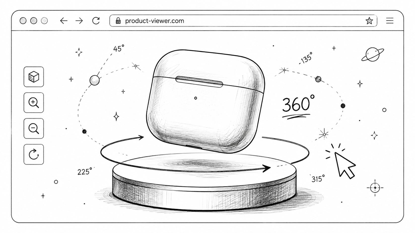
A turntable is a sequence in which the camera or object rotates around a fixed center, usually while lighting and framing remain consistent. A 360-degree view can mean a complete horizontal rotation, or, in a broader interactive sense, access to angles around the object including top and underside views. Clarify the scope before estimating exports, because a horizontal spin and a full spherical inspection aren't the same deliverable.
Match the rotation to the channel
A turntable can become several useful assets:
- MP4 or WebM: A looping product rotation for a landing page.
- GIF preview: A compact marketplace or social preview.
- Image sequence: Individual frames for an AR viewer or interactive component.
- Contact sheet: A grid of stills for client review, approvals, or catalog selection.
A junior artist often treats the frame count as a purely technical setting. It's better to treat it as a communication decision. The rotation should reveal meaningful changes in silhouette, material response, and component relationships without making the viewer wait through redundant positions.
Lighting consistency matters more than many artists expect. If the key light changes between frames, the object appears to flicker. Low-quality shadow sampling can create unstable edges, and a material that only looks correct from the front can expose roughness, texture seams, or incorrect normals as the model turns.
For examples of the workflow, explore 360-degree turntable export. If you're building a guided presentation rather than a simple product spin, creating 3D video tours with AI may help you plan a more narrative sequence around the object.
The video below is useful when you want to show motion as part of the explanation rather than relying on a single still.
A good turntable keeps the model centered, maintains a stable horizon, and preserves the same exposure across the sequence. Before rendering, rotate through the material previews and inspect the back, underside, and connection points. A spin earns its place when every segment answers a question that a still image leaves unresolved.
Matching the Right View to the Right Job
Start with the deliverable, not the software. The same object may need an orthographic reference set for the modeler, a technical sheet for manufacturing, a perspective image for marketing, and a turntable for the product page.
This compact framework gives each job a default starting point.
| Job | Recommended View | Camera / Setting | Export Format |
|---|---|---|---|
| Modeling and sculpting | Front, side, and top orthographic views | Orthographic camera, aligned to the main axes | PNG reference sheets or viewport captures |
| 3D printing | Orthographic views plus a bottom or rear check | Orthographic camera, inspect orientation and supports | STL or 3MF model with technical reference images |
| Manufacturing review | Dimensioned front, side, and top projections | Orthographic camera with consistent scale | PDF drawing or high-resolution raster sheet |
| Product presentation | Perspective hero angle | Perspective camera with controlled lens and lighting | PNG, JPEG, or rendered video |
| Technical illustration | Isometric view | Parallel projection with balanced axis visibility | SVG, PNG, or illustration-ready render |
| Web and interactive use | Turntable or interactive multi-angle viewer | Fixed center, consistent lighting and framing | WebM, MP4, image sequence, or 3D web asset |
Four quick decisions
For modeling, use the reference-grid mindset. The front, side, and top views should agree, and each should expose a different proportion problem.
For printing, don't substitute a beautiful perspective image for a dimensional check. The view must help you judge the build orientation and physical consequences of the mesh.
For presentation, ask whether the audience needs emotion or comparison. Perspective carries atmosphere. Isometric preserves a clean relationship between parts.
For web delivery, consider whether the customer needs control. An interactive viewer or turntable can let them inspect the feature that your marketing team didn't know they cared about.
When you need to plan a set of product angles rather than improvise them, this practical angle guide from Bulk Image Generation can help organize the selection around the subject and intended use.
The key is to name the decision before opening Blender, Maya, ZBrush, or a render tool. Once the job is clear, the camera setting and file format become much easier to choose.
Why More Views Are Not Always the Answer
More views can improve understanding, but only when each view contributes new information. A recognition system may become more accurate as it receives additional rendered perspectives. A 2024 review of deep models for multi-view 3D object recognition found that 25 of 37 reviewed works used circular camera layouts and 14 used spherical layouts. The review also reports that 4, 6, 8, or more views often improve classification quickly, with 20 views supporting state-of-the-art performance in several methods. The multi-view recognition survey shows that view selection is measurable, not merely aesthetic.
That research doesn't create a universal export rule for artists. A viewer evaluating a single product doesn't need every technically possible angle. Too many nearly identical frames can dilute the focal feature, increase page weight, and make a client spend attention on repetition instead of decisions.

Optimize for coverage, not volume
Reconstruction benchmarks make the same point from another direction. In the Multi-Sensor Large-Scale Dataset benchmark, the precision-oriented method VisMVSNet reached 32% accuracy on all scenes and exceeded 80% accuracy on just 14 scenes, while the recall-oriented ACMP reconstructed all scenes with at least 53% recall at a 0.5 mm threshold. The CVPR benchmark paper illustrates the tension between covering the object and recovering fine surface detail.
A separate ETH3D-based study reported an F1-score of 80.11 at 2 cm, compared with 76.15 for OpenMVS and 67.66 for COLMAP, and reported runtime of more than 4× faster than competing methods. The DP-MVS study reinforces a practical lesson: well-conditioned views matter. Raw image count can't compensate for occlusion, weak texture, or poor camera geometry.
Trim a view set by asking:
- New geometry: Does this angle reveal a previously hidden surface?
- New decision: Does it help someone approve, model, print, or buy the object?
- New material behavior: Does the surface response change in a useful way?
- New ambiguity: Does it distinguish similar parts or clarify an overlap?
If the answer is no, cut the angle. A disciplined set often includes the orthographic trio plus one strong perspective view, then adds only the views needed to expose a hidden feature or support an interactive inspection.
A further complication is that extra views don't automatically solve identity problems. Similar objects can remain difficult to distinguish when they share shape, material, or pose, and recent work on visual lookalikes uses semantic priors to separate confusing pairs. More images help only when they add discriminating evidence.
Sculpty gives you a browser-based workflow for generating, texturing, remeshing, rendering, and exporting 3D assets, including multi-view-to-3D reconstruction from several angle images and 360-degree turntable output. Visit Sculpty to test a view-driven asset workflow before your next modeling, printing, or product presentation project.