
How to Convert STL to 3MF Without Losing Data
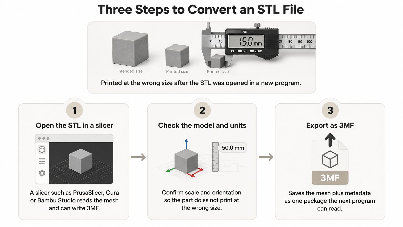
Your printed bracket fits in the palm of your hand, but it was supposed to span the mounting holes on your machine. The STL looked normal when you opened it in a different program. Somewhere between import and printing, the software interpreted its size incorrectly.
To convert STL to 3MF without losing useful data, treat conversion as a checked handoff, not just a change of file extension. Confirm the dimensions, inspect the mesh, save the right kind of package, and test what your actual slicer reads back.
Table of Contents
- Three Steps to Convert an STL File
- What an STL Loses That 3MF Keeps
- Matching Units Before You Export
- Mesh Problems to Fix Before Converting
- Features Your Slicer May Drop
- Keep the STL and Test the 3MF Before Printing
Three Steps to Convert an STL File
A wrong-size print can start with a perfectly readable mesh. Before changing formats, find a trustworthy reference dimension, such as a drawing measurement or the intended distance between mounting holes. Without that reference, you can preserve the imported size without knowing whether it's correct.
The basic workflow is straightforward, but the checks matter as much as the export command.
Open the STL in the tool you'll use next. For print preparation, start with PrusaSlicer or Bambu Studio. If you need to work alongside a CAD design, insert the mesh into Autodesk Fusion. Pay attention to import prompts, especially automatic resizing or unit selection. Don't accept a suggested scale change just because it makes the model fit the plate.
Check dimensions, orientation, and placement. Select the model and inspect its overall dimensions. Compare a known feature with the intended measurement, then confirm the correct face points toward the bed. For separate parts, inspect the object list as well as the viewport. Overlapping components can hide a missing or incorrectly positioned part.
Save as 3MF, then reopen the saved file. In a slicer, use the File menu's project-saving or 3MF export command. Choose deliberately between a project containing the plate setup and a model-only export. In Fusion, use Save As Mesh and select 3MF. Save beside the original STL, close the working document, and reopen the saved package to verify the result.
Choose the route by what you need to retain
A slicer project is useful for preserving a prepared build. PrusaSlicer and Bambu Studio can save placement and application-specific print configuration, but a geometry-only export isn't equivalent to saving the whole project. Inspect the command's scope before clicking Save.
Fusion is more useful when the mesh belongs in a design workflow. Check the document and export units explicitly rather than assuming the output inherits everything correctly. Exporting an imported STL won't recreate editable CAD features.
Browser converters are convenient for a one-off file, especially when you don't need a complete slicer project. Check upload privacy, retention policies, and unit handling first. If a service doesn't document whether it retains placement or materials, record that capability as unknown, not supported.
The 3MF Consortium's discussion published by 3DPrint.com described 3MF in 2024 as an open additive-manufacturing exchange standard with growing industrial and consumer adoption. That makes it a useful handoff format, but adoption alone doesn't verify your export.
What an STL Loses That 3MF Keeps
Units are the most consequential difference for an ordinary print. An STL contains coordinates, but it doesn't natively identify their physical unit. The receiving application has to interpret them, which leaves room for a correctly shaped model to acquire the wrong size.
The 3MF Consortium describes the shift from STL, introduced in 1987, to 3MF, introduced in 2015, as a move from triangular surface data toward a manufacturing-oriented package. STL stores triangular facets in ASCII or binary form; 3MF packages XML in a compressed ZIP-like container that can carry geometry alongside units, placement, materials, and build information.
Data each format keeps
| Data | STL | 3MF |
|---|---|---|
| Units | No | Yes |
| Triangle geometry | Yes | Yes |
| Colours and materials | No | Yes, through material extensions |
| Object placement and build items | No | Yes |
| Assembly structure | No | Yes |
| Printer or print settings | No | Application-specific project data |
The distinction between format capability and saved content matters. A 3MF package can hold assembly relationships, but the exporting application must write them. Likewise, printer settings saved by a slicer are not a universal printer profile that every other application can apply.
An STL can contain disconnected surfaces within its triangle data. That's different from preserving named parts, assembly relationships, or intentional build items. After import, check whether the application treats those surfaces as separate objects or as shells inside a single object.
Practical rule: Conversion can add information you supply. It can't recover information the STL never contained.
Preserve the source when appearance matters
Say you receive a plain STL of a figurine that originally had painted clothing and separate accessories. Saving it as 3MF won't reveal those original colour assignments. You'll need to assign them again or obtain a richer export from the source design.
The same limitation applies to curved surfaces. A new container doesn't turn a faceted mesh back into the original CAD surface, and it doesn't restore an editable feature history.
If you're deciding what to request from a designer, this guide to file types used by 3D printers helps separate geometry exchange from print preparation. Request a direct source export when colours, materials, or assemblies matter, rather than deliberately passing the design through STL first.
Matching Units Before You Export
Suppose a model intended to measure ten centimetres across appears as ten millimetres after import. The shape may look convincing in the viewport, particularly if the application zooms to fit it. The dimensional readout, not its apparent screen size, exposes the problem.
The safest approach is to compare a known measurement before applying any scale correction. Don't enlarge a part until it looks plausible, and don't assume that fitting the build plate proves anything about its intended dimensions.
Unit conversion factors for 3MF export
Use this table to identify the source unit, then use the application's unit conversion controls rather than guessing a scale multiplier.
| Unit | Where you usually see it |
|---|---|
| Micron | Micro parts and jewellery masters; confirm the source's declared unit |
| Millimetre | Slicer workflows and mechanical CAD projects |
| Centimetre | Hobby models and some toy designs |
| Inch | Imperial mechanical parts and US-based design workflows |
| Foot | Large architectural or display models |
| Metre | Architectural and large-scale models |
These are clues, not reliable declarations. A filename or model category can suggest a unit, but the drawing, source document, or creator's stated dimensions should decide it.
Measure a feature you can identify
For a hypothetical check, use a test block intended to be twenty millimetres wide. Select it after import and compare the displayed width with that intended value. On a real part, choose an equally unambiguous feature, such as a flat outside edge rather than a diagonal bounding box.
If the measurement is wrong, correct the import unit or apply a calculated uniform scale. Check that the application hasn't already resized the model automatically, otherwise you may apply the correction twice.
Set the intended physical size first. Save the unit declaration only after the coordinates and dimensions agree.
Changing a unit label and converting a model's dimensions aren't always the same operation. Inspect the resulting measurement whenever you change either setting.
For an imperial bracket, select the source unit explicitly rather than accepting a millimetre assumption. Keep the whole project in a consistent working unit, include that unit in the filename, and verify the exported size before sharing the file.
Mesh Problems to Fix Before Converting
An open-edge or non-manifold warning deserves attention before export. A converter may successfully package triangles that don't describe a closed printable volume. Successful file creation only tells you the program wrote a file, not that the slicer will interpret every surface as intended.
Start with the slicer's repair function, then inspect the changed region. Automatic repair can close an accidental gap, but it can also cap an opening that belongs in the design. A clean status message isn't enough when the repair changes a functional feature.
Conversion symptoms, causes and fixes
| Symptom | Likely cause | Fix |
|---|---|---|
| Non-manifold or hole warnings | Open edges from the STL export | Run auto-repair in the slicer or a mesh editor, then re-export |
| Model prints tiny or huge | Unit mismatch on import | Set the correct import unit and rescale to the target size |
| Missing or dark faces | Flipped normals | Recalculate normals in a mesh editor before exporting |
| Colours or materials missing | Source STL had none | Assign colours in the slicer after conversion |
| Model floats above the bed | Build placement lost | Use Place on Bed or auto-arrange before slicing |
| File very large or slow to load | Dense mesh from AI or scan output | Decimate or remesh to a chosen target triangle count |
For a closer diagnosis of shared edges and invalid surfaces, use this explanation of non-manifold geometry. Fix the underlying mesh rather than repeatedly exporting the same warning into a different container.
Separate surface repairs from geometry changes
In Blender, inspect face orientation and recalculate outward-facing normals where appropriate. If a region still appears inverted, examine whether internal faces or overlapping shells make the intended outside ambiguous. Recalculating normals alone won't resolve every topology problem.
Hole filling, remeshing, and decimation can change geometry. Keep an untouched source and save the repaired version separately. After repair, compare mounting holes, thin walls, sharp edges, and mating surfaces against the original.
Decimation is useful when a dense scan or generated mesh makes the slicer awkward to use. Choose a target triangle count, inspect the result, and reduce further only if the surfaces still meet your needs. Don't chase a smaller file at the expense of a round bore or a detailed face.
Repair checkpoint: Inspect both the outer shape and the internal openings. A watertight mesh can still describe the wrong part.
Finally, slice the repaired model and examine the layer preview. Look for missing walls, unexpected filled cavities, unsupported islands, and disappearing thin features. Those checks reveal printing problems that a shaded viewport can conceal.
Features Your Slicer May Drop
Saving as 3MF doesn't guarantee a complete transfer between applications. The 3MF specification suite includes core mesh support and extensions for materials, production data, slices, boolean operations, beam lattices, and volumetric representations. An available extension isn't proof that your slicer reads or preserves it.
Use the distinction below as a reminder to test beyond basic geometry.
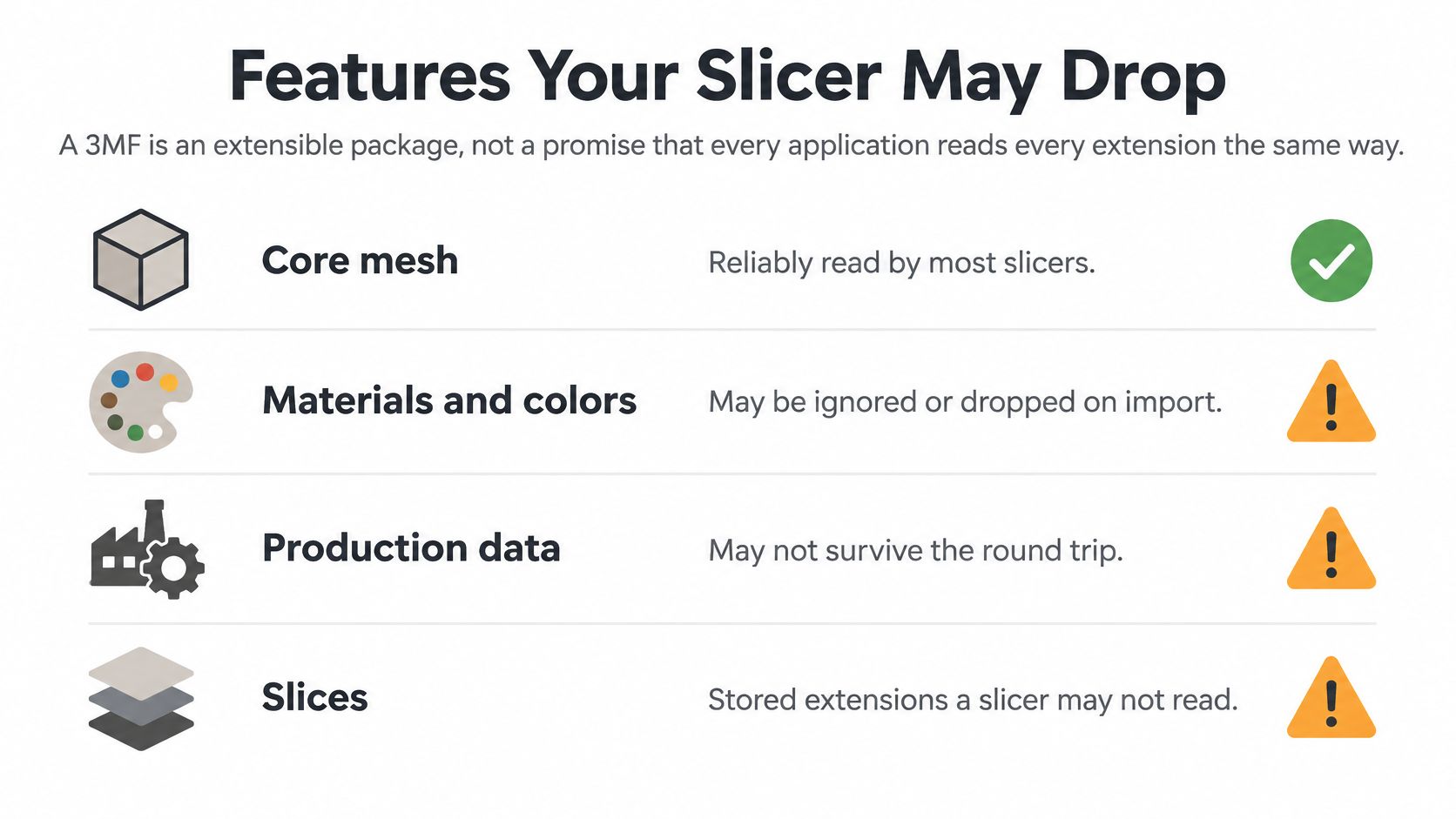
Feature test checklist for the target application
Create a hypothetical sample containing a pair of separate objects, an assigned colour, and a known dimension. Export it through the same route you intend to use for the actual job.
| Feature | Why it matters | Test in the target app |
|---|---|---|
| Units | Sets the real size of the part | Measure a hypothetical twenty-millimetre test block after reopening |
| Object count | Keeps multi-part plates intact | Count objects and inspect their grouping after import |
| Colours and materials | Needed for multi-colour printing | Check surface colours and material assignments |
| Build items and placement | Preserves the intended arrangement | Confirm position and orientation after import |
| Thumbnails | Shows a preview in the library | Look for the saved preview image |
| Print settings | Reuses the intended slicer configuration | Compare the selected printer, layer height, infill, and supports |
| Custom metadata | Tracks project information | Inspect a deliberately added project field after import and re-export |
Record the outcome as preserved, changed, or missing. A coloured viewport doesn't prove the correct filament assignment survived, and a familiar printer name doesn't prove the destination applied the intended profile.
Test the actual handoff
Use the exact destination application, including its normal import mode. If it offers to open the file as a project or import geometry only, test the option your recipient will choose. These routes can produce different results from the same package.
This accompanying video provides another reference while you inspect your workflow.
When choosing slicing software for 3D printing, include this small compatibility test in your evaluation. Keep the original mesh, record the conversion tool and version, and document any settings the recipient must recreate manually.
Newer capabilities, including volumetric representations, expand what a package can describe without making support universal. Repeat the test after software updates, especially when a workflow depends on more than mesh geometry.
Keep the STL and Test the 3MF Before Printing
Convert when you need a verified manufacturing package, not because the newer extension looks preferable. Before releasing a file to another person or printer, leave a small, understandable audit trail.
- Archive the original STL untouched. Put it in a source folder, separate from repaired meshes and print-ready exports.
- Name the working package clearly, for example
bracket_mm_prusaslicer.3mf. Record the application version in a companion note. - Reopen the saved package independently. Measure a known feature against the source drawing or intended dimension.
- Run the destination application's feature checks and inspect its sliced preview. Record anything that needs manual setup.
- For a functional part, print a small representative test piece containing the critical fit before committing to the full build.
For work that also involves physical packaging, Mylarmen's packaging brief to production checklist is a useful companion for organizing that separate handoff. Keep packaging requirements distinct from the model's print settings so each recipient gets clear production instructions.
If the generator project or CAD source still exists and supports suitable 3MF export, export directly from that source. There's no benefit in deliberately discarding source information through an intermediate STL. An STL you already hold still needs the import, inspection, and verification workflow.
Keep your test package with the project and rerun it whenever the slicer or printer software changes. That gives you a repeatable check instead of relying on memory.
Sculpty offers browser-based text-to-3D and image-to-3D generation, remeshing tools, and exports including STL and 3MF. Visit the studio to prepare your next model, then verify its dimensions, mesh, and exported package in your printing slicer before committing to the build.