
Reduce STL File Size: Methods That Keep Models Accurate

The most common advice for reducing an STL file is to decimate it. That's often the wrong first move: deleting triangles can damage features, while converting the file to binary or removing geometry that won't appear in the print can shrink it without sacrificing visible detail.
Set a deviation budget before you simplify the surface. Then remove hidden geometry, export as binary if possible, and decimate only as far as the part's tolerances allow.
Table of Contents
- Size Reduction Methods Compared by Risk
- Triangle Count and Expected File Size
- Setting a Deviation Budget Before You Cut
- Reduce Triangles Step by Step
- Fixing Failures After Reduction
- Choose Your Reduction Path Before You Export
Size Reduction Methods Compared by Risk
The riskiest reduction method is the one that removes triangles from features your part must preserve. Start with changes that leave the surface intact, then remove geometry that will not appear in the print. Decimation is the last step because it alters the mesh.
| Method | Typical size change | Geometry impact | Best use |
|---|---|---|---|
| Convert ASCII to binary STL | Often substantially smaller | None, same triangles | Any job that accepts binary STL |
| Remove hidden and internal geometry | Depends on how much unnecessary geometry is present | Removes geometry that does not contribute to the finished part | Models with cavities or unused parts |
| Decimate with quadric edge collapse | Can substantially shrink a dense mesh | Reduces triangles while aiming to retain visible detail | Scans and high-poly sculpts |
| Subdivide after decimating | Larger file | Adds triangles without restoring removed detail | Avoid |
Removing interior faces, overlapping shells, or components that will not be printed can cut file size without changing the required outer surface. The benefit depends on how much of that geometry the model contains. A mesh made only of the surface needed for the print has little to gain from cleanup.
Quadric edge collapse is useful when the visible mesh itself is too dense. It removes triangles more readily from flatter regions, which helps retain curvature and edges better than uniform deletion. The trade-off is that fine features can still soften, so set the permitted deviation from the part's tolerance before reducing the mesh.
Subdividing after decimation increases the triangle count without recovering the detail that was removed. Use format conversion and geometry cleanup first. Decimate only when the remaining file size is still a problem and the part can tolerate the surface change.
Triangle Count and Expected File Size
A binary STL uses 50 bytes per triangle, after an 84-byte header. That makes its size easy to estimate from the triangle count; a model with 1,000,000 triangles takes about 50 MB before filesystem rounding. ASCII STL stores coordinates as readable text instead, and commonly takes three to five times more space, as explained in Markforged's STL guidance.
| Triangle count | Binary STL size | Typical ASCII size | Practical use |
|---|---|---|---|
| 100,000 | 5 MB | 15–25 MB | Desktop prints and light game props |
| 500,000 | 25 MB | 75–125 MB | Detailed prints and mid-size game assets |
| 1,000,000 | 50 MB | 150–250 MB | High-detail sculpts above the 20 MB guideline |
| 2,000,000 | 100 MB | 300–500 MB | Dense sculpts that need decimation |
Files above 20 MB are worth reducing when practical because oversized models can slow upload, loading, and slicer preparation. Binary conversion is the straightforward first check: it can make a substantial difference without altering the mesh. But binary STL is already close to its minimum raw STL representation. Once you've converted it, removing metadata won't usually produce another major reduction. The main remaining lever is triangle count.
Before choosing a reduction target, find the triangle count in your modeling or mesh software's statistics or information panel. Compare that count with the table to see whether a binary export is likely to be enough or whether you'll need to simplify the mesh.
Setting a Deviation Budget Before You Cut
A smaller STL is not a better part if decimation pushes a critical surface outside tolerance. Set the deviation limit first, using the strictest constraint from the part's manufacturing tolerance, critical feature size, and printer resolution allowance. Then compare the simplified surface with the original using Hausdorff distance or maximum surface deviation.
| Faces kept | Mean deviation | 99.9th percentile deviation | When to use |
|---|---|---|---|
| 50% of faces, about 50% smaller | 0.003 mm | 0.021 mm | First test when the result stays within the deviation budget |
| 25% of faces, about 75% smaller | 0.007 mm | 0.042 mm | Try only if the 50% reduction stays within the budget |
| 10% of faces, about 90% smaller | 0.016 mm | 0.100 mm | Display models where fine detail does not matter |
The mean can hide a localized error. The 99.9th-percentile deviation gives a better warning for mating faces, narrow fillets, and other areas where a bad patch can spoil fit. The deviation-tolerance guide reports benchmark measurements that illustrate why checking the mean alone can miss those problem areas.
A 2023 study of four CBCT-derived maxillofacial datasets reported no 3D deviations after a 50% reduction, minor deviations after a 75% reduction, and more pronounced deviations after a 90% reduction, particularly in head and skull models. Those results apply to the examined models, not every part or material.
Start with a 50% reduction and measure its deviation against your limit. If it passes, test 25% of the original face count and measure again; if it fails, keep the less aggressive result or use a smaller reduction step. Check dimensions and watertightness, preserve boundaries and normals, and inspect curves and mating surfaces. A smooth viewport appearance does not prove that the finished part remains within tolerance.
Reduce Triangles Step by Step
A smaller STL is not automatically a better model. Set the allowable deviation from the part's tolerance first, then remove hidden geometry before reducing triangles on surfaces that affect fit or appearance. Keep the original file untouched and make one change at a time so you can trace any failure to cleanup, decimation, or export.
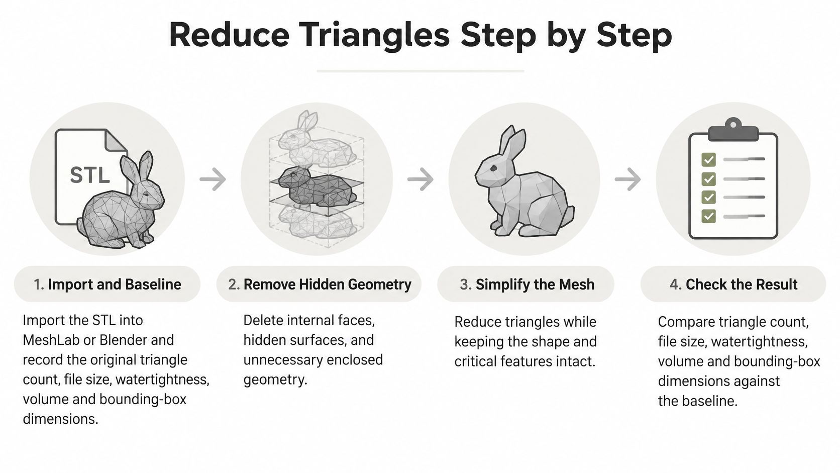
Import and record a baseline. Open the STL in MeshLab or Blender. Note its triangle count, file size, watertightness, volume, and bounding-box dimensions. These give you concrete checks after each edit.
Remove geometry that does not contribute to the finished part. Delete hidden internal faces, unused components, and unnecessary enclosed geometry before simplifying the visible surface. Remove isolated components, duplicate faces, and degenerate faces as well. This reduces mesh data without spending your deviation budget on surfaces that need to remain accurate.
Apply targeted decimation. In MeshLab, use Quadric Edge Collapse Decimation; in Blender, use a Decimate modifier in Collapse mode. Start by retaining half the triangles. Enable boundary, normal, and topology preservation, along with optimal vertex placement, where those options are available. For more on choosing a method and setting, see this guide to mesh decimation.
Quadric-error decimation tends to remove more triangles from flatter, lower-curvature regions while preserving important features. Use the 50-bytes-per-triangle rule to estimate binary STL size: 69,451 triangles produce a file of about 3.4 MB. Retaining half the triangles roughly halves that size, to about 1.7 MB.
Export and verify. Export as binary STL, reopen the exported file, and compare its manifoldness, normals, scale, dimensions, and deviation with the baseline. Reopening catches export errors before slicing. A model can look smooth in the viewport while exceeding the tolerance that matters to the finished part.
Judge the result by measured deviation, not by the reduction percentage shown in the tool. Stop when the mesh meets the part's tolerance; cutting more triangles can soften edges or distort thin features without improving the finished part.
Fixing Failures After Reduction
Removing hidden geometry can be a safer first move than aggressively deleting visible polygons. It eliminates data that won't contribute to the printed surface, while preserving the shape you need. Mesh cleanup still requires care, though: a model can look intact in the viewport and contain defects that appear only after export or during slicing.
Repair the problem you can see
- Broken triangles or holes: Fill holes and inspect the surrounding surface before exporting again. If the damage appeared after decimation, rerun with boundary preservation enabled or use a less aggressive setting.
- Flipped normals: Recalculate normals, then reopen the exported STL to confirm the surface is oriented consistently.
- Softened sharp edges: Reduce the decimation strength around critical edges or preserve those boundaries in the simplification settings.
- Thin walls or small components: Back off the reduction ratio. These features can disappear or become distorted before the main silhouette looks noticeably different.
Excessively fine meshes can also make slicers crash or struggle during preparation. A smaller, cleaner mesh can be more reliable as well as lighter, but shrinking the file alone won't fix non-manifold geometry or incorrect dimensions. For a focused repair workflow, use this guide to identify and correct non-manifold geometry.
Keep the process controlled:
- Save a separate working copy. Keep the original as the reference for dimensions and recovery.
- Change one variable per run. Don't combine a repair, major decimation, and scale change in one pass.
- Check a known dimension. Measure the exported part against a dimension you trust before relying on its scale.
- Slice the final export. Don't assume that a model that looks acceptable on screen will behave correctly in the slicer.
A heavily reduced mesh may look fine in a viewport but still fail during slicing. Treat the slicer check as part of the reduction, not an optional step afterward.
Choose Your Reduction Path Before You Export
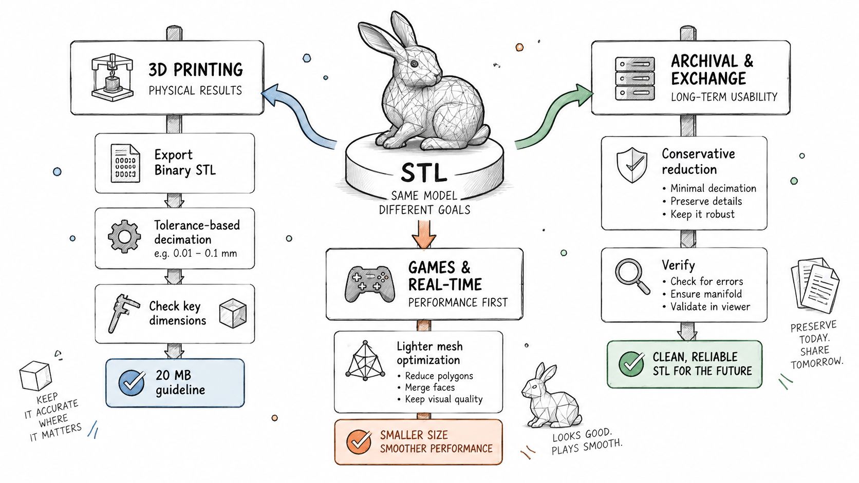
The right reduction depends on what the mesh has to do. Start with the intended use, then decide how much surface detail and topology to preserve.
For 3D printing, protect dimensions and fit. Export binary STL, remove geometry that won't be printed, then decimate only within the part's deviation budget. Check walls, openings, and mating surfaces in the final slicer. If you're deciding whether another mesh format better fits your workflow, compare the practical differences in this guide to STL and OBJ.
For games and real-time engines, prioritize useful topology. A dense scan may need cleanup, remeshing, or retopology before decimation; deleting triangles from a messy mesh can leave poor topology behind. Confirm the imported triangle count and check the asset in the engine, then export in a format that the project accepts.
For presentation or client review, prioritize fast viewing. A lighter model is easier to share and inspect, but keep a high-detail master file for later edits or manufacturing. Preview the exported version in a viewer that supports the format before sending it.
The reduction workflow can be performed in a dedicated mesh editor or in a web-based 3D studio with remeshing and retopology tools. Whatever tool you choose, record the original file size and triangle count, then note the final deviation and check the exported mesh before handing it off.
Here's a short video to help you judge the reduction process in practice.
This week, run the workflow on one oversized STL and record its starting size, triangle count, and dimensions. Compare those with the exported file and its measured deviation before you use it for printing or delivery.
Use Sculpty to generate and refine 3D assets with remeshing, retopology, and exports for downstream workflows. Try it with an oversized model to prepare a cleaner mesh, then verify the exported STL against your tolerance and slicer checks.