
Layer Height 3D Printer Settings: Quality vs Print Speed
Fifty-two experimental trials in inkjet-based 3D printing measured average printed layer heights from 4.73 micrometres to 98.58 micrometres, a span of roughly 20.8 times between the thinnest and thickest result in the same process (Virtual and Physical Prototyping layer height study). A span that wide is a manufacturing parameter, and it shifts with machine, material and job.
Treat layer height like gear selection. A low gear climbs cleanly but slowly; a high gear covers ground fast and feels coarser. On a layer height 3D printer, finer layers mainly buy vertical smoothness, and the bill arrives in hours. They do not automatically deliver stronger parts, tighter dimensions or better fit.
The useful question is which feature matters most: surface, fit, strength or time. A curved display piece, a press-fit boss and a bracket fail in different ways, so the right setting follows the job. That matters even more for curved AI-generated meshes, where one uniform height can leave visible steps on shallow curves while wasting effort elsewhere. Start from the feature that matters, then let nozzle range and a short test print settle the number.
Table of Contents
- Recommended Layer Heights by Print Goal
- How Layer Height Trades Print Time for Detail
- Why Thinner Layers Are Not Always Stronger
- Matching Layer Height to Nozzle Diameter
- Setting Layer Height for Curved AI-Generated Meshes
- Layer Height for Resin Printers
- Confirm Your Layer Height With a Test Print
- Layer Height Problems and How to Fix Them
Recommended Layer Heights by Print Goal
Print goals map to layer heights more reliably than printer brands do. Find the row that matches what the part has to do, then read across to the nozzle and the reason behind it.
| Print goal | Layer height | Typical nozzle | Why |
|---|---|---|---|
| Fast drafts and fit checks | 0.30 mm | 0.4 mm | Shortest time, rougher surface acceptable |
| General prototypes | 0.20 mm | 0.4 mm | Balance of time, detail and strength |
| Visible detail and miniatures | 0.10 mm | 0.4 mm | Less stair-stepping on curves |
| Demanding interlayer strength | 0.10 mm with longer annealing | 0.4 mm | Highest tensile result in tested PLA and PETG |
| Fine features | 0.05-0.10 mm | 0.2 mm | Resolves small details and thin relief |
| Large structural parts | 0.40-0.60 mm | 0.6-0.8 mm | Throughput over surface detail |
Why the Middle Row Earns the Default
0.20 mm on a 0.4 mm nozzle sits in the middle of the valid range, so the extruder lays down a layer that bonds reliably without spending a full day on a bracket. It resolves most shapes well enough that a casual viewer won't notice the layer lines, and it keeps the print inside an evening. When a student has no strong reason to pick otherwise, this is the row I point at.
The 0.10 mm row is the one people reach for first, and it's usually the wrong first move. It improves vertical smoothness on curved surfaces and it does little else by itself. A part printed at 0.10 mm is not automatically stronger, not automatically tighter on a mating hole, and not automatically more accurate where the calipers land.
Practical rule: the finest layer your printer claims to support is a capability, not a recommendation. Start from the goal and work backwards to the number.
Which Column You Change First
Two variables sit in that table, and they aren't interchangeable. The nozzle sets the minimum feature width, the extrusion line width and the practical floor of your layer height. The layer height sets vertical resolution and print time. Change the layer height and you change how long the print takes. Change the nozzle and you change what geometry can exist at all.
For a miniature with a nose 0.3 mm wide, no layer height rescues the print on a 0.4 mm nozzle. The nozzle has to change first. For a hidden bracket that just needs to exist by morning, the 0.4 mm nozzle is fine and the layer height carries the decision.
Start by naming the feature that has to work. If it's a visible curve, the layer height leads. If it's a slot, a pin or a thread, the nozzle leads and the layer height follows inside the range that nozzle supports. Then note which single column you adjusted, because untangling two changes at once during troubleshooting is miserable.
How Layer Height Trades Print Time for Detail
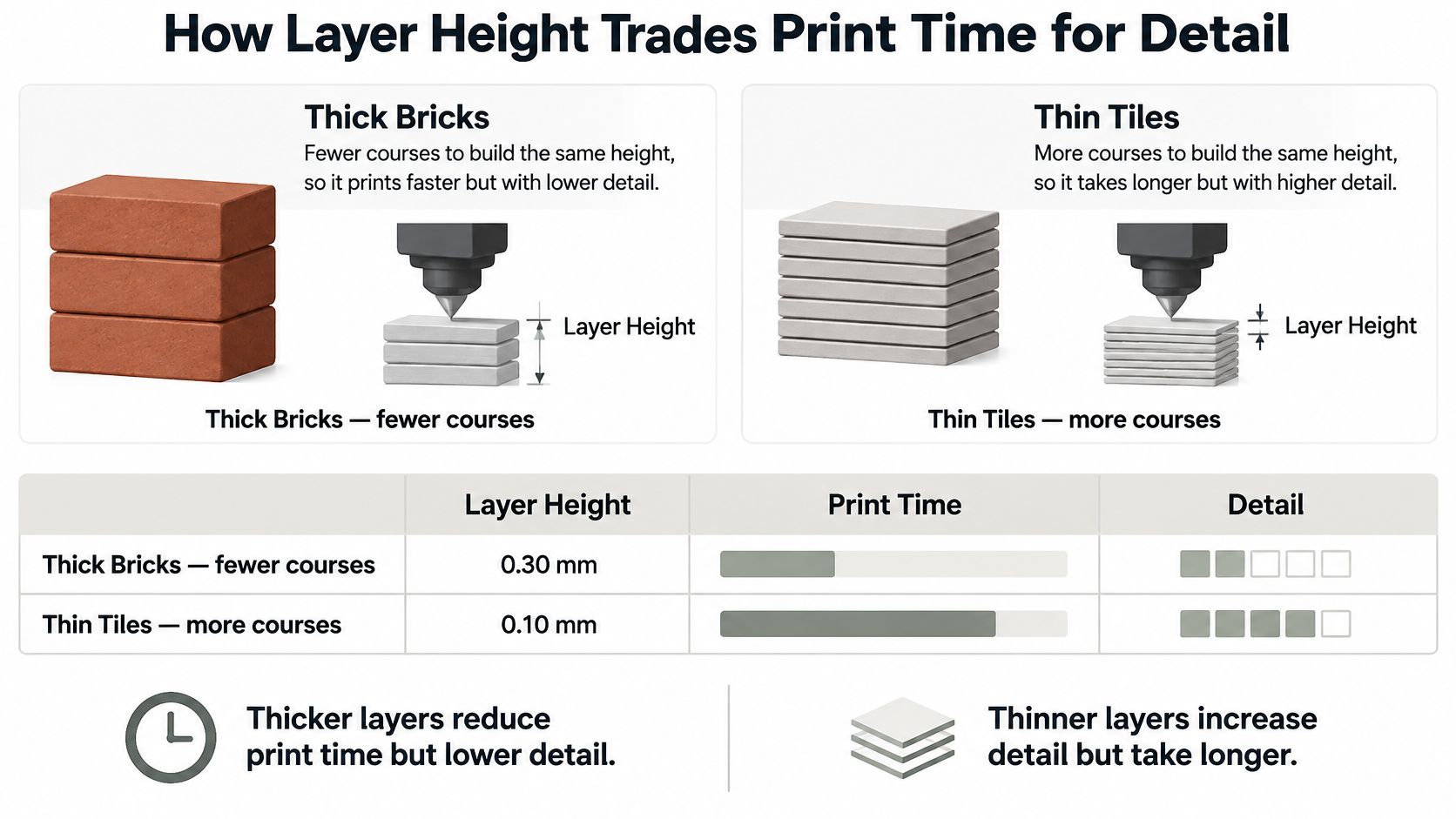
Layer height is the vertical thickness deposited or cured in one pass. The clearest analogy is a wall: thick bricks reach the same height in fewer courses, so the wall goes up quickly, and every course shows as a visible step. Thin tiles take far more passes, and the steps nearly disappear.
A fused-filament-fabrication experiment pushed that trade to its limits. Testing layer heights from 0.02 mm to 0.40 mm, it measured print time falling from 1.18 hours to 0.10 hours, approximately a 91.5% reduction, because thicker layers build the same object in fewer passes (IOP Conference Series on FFF layer height). Same geometry, same machine, one dial.
| Layer height | Print time | Trade-off |
|---|---|---|
| 0.02 mm | 1.18 hours | Finest vertical detail, longest print |
| 0.40 mm | 0.10 hours | Roughest surface, shortest print |
Read the table against the layer count. A twenty-fold increase in layer thickness produced roughly a twelve-fold drop in time. The gap comes from fixed motions in every pass: travel moves, retractions, perimeter slowdowns. Thicker layers skip passes, and each remaining one still carries that overhead, so savings flatten instead of scaling perfectly.
Where Extra Thickness Stops Paying
The detail zones are worth memorizing. Layers between 0.05 and 0.10 mm reveal finer vertical detail and soften visible stair-stepping on curves. Layers between 0.20 and 0.40 mm improve throughput and leave a rougher surface. Below roughly 0.05 mm on a standard FDM machine, each additional hour buys less and less visible improvement, because the steps are already too small for the eye to catch at arm's length.
Resin prints follow the same curve at different magnitudes. Thicker layers shorten a vat print because the platform runs fewer lift-and-cure cycles, while resin use stays nearly flat: the part holds the same volume either way. In both processes, layer height moves machine hours far more than it moves material consumption.
That ratio is why the setting earns attention on long jobs and almost none on ten-minute ones.
The method that follows is simple. Pick the feature the part lives or dies on, then choose the thickest layer that still protects it. A bracket hidden inside an assembly earns the coarse end of the range. A display piece photographed up close earns the fine end. A surface headed for sanding, filler and paint needs nothing finer than its roughest acceptable neighbor, because the finishing work erases the steps you paid hours to avoid.
Why Thinner Layers Are Not Always Stronger
"Thinner layers mean stronger parts" sounds like physics. It's a half-truth that costs people a lot of hours.
A controlled study compared 0.10, 0.20 and 0.30 mm layers in PLA, PETG and carbon-fiber-reinforced PETG and found that layer height had a larger influence on tensile strength than the annealing variables tested (PMC study on layer height, annealing and mechanical behavior). So far, so predictable.
Then the results split.
Two Properties, Two Winners
The best dimensional accuracy in that study came from a higher 0.30 mm layer height combined with short annealing. The strongest tensile results came from 0.10 mm layers combined with longer annealing. Same printer, same materials, opposite answers, because accuracy and strength are different properties.
The mechanisms compete. Thinner layers can improve interlayer contact and reduce geometric discontinuities, which helps bonding. Thermal history, extrusion width, cooling, orientation and material crystallinity can outweigh that effect entirely. A thin layer that cools unevenly bonds worse than a thick layer that stays hot enough to fuse.
Which property does your part fail on? Surface, fit, strength or time. Pick the layer height that protects that one, and accept the cost somewhere else.
Thinner layers can improve dimensional accuracy on some machines, but very small layers also lengthen print time and can aggravate oozing or stringing when filament flow isn't tuned. The same number that helped one machine hurt another, which is the tell that the number isn't the whole story.
For functional parts, the honest test is a calibration coupon loaded in the direction the part will experience, measured with calipers. Appearance under a desk lamp tells you nothing about whether a boss will shear off. And before you spend an afternoon chasing layer height, check the geometry doing the key work: wall count and wall thickness in 3D printing usually improve strength more than a single layer step does.
Matching Layer Height to Nozzle Diameter
The nozzle is the constraint that makes the layer height legal, and most "my printer won't do 0.08 mm" problems are really "my nozzle is 0.4 mm" problems. The working guideline is to keep layer height between roughly a quarter and three quarters of the nozzle diameter. Below a quarter, the extruder struggles to meter filament consistently. Above three quarters, the layer has too little contact with the one beneath it and the bond weakens.
- 0.2 mm nozzle: roughly 0.05 to 0.15 mm. Resolves fine relief and small text, but prints slowly and clogs more readily on filled filaments.
- 0.4 mm nozzle: roughly 0.10 to 0.30 mm. The desktop default, wide enough for structural work and fine enough for most detail.
- 0.6 mm nozzle: roughly 0.15 to 0.45 mm. Noticeably faster on brackets, enclosures and anything with thick walls.
- 0.8 mm nozzle: roughly 0.20 to 0.60 mm. Large, rough, high-throughput parts where surface finish is a low priority.
Two rules follow from those ranges. Wall thickness should be a whole multiple of the extrusion width, so a 0.4 mm nozzle lays two clean perimeters at 0.8 mm or three at 1.2 mm rather than leaving a thin sliver the slicer has to improvise. And any feature narrower than the nozzle won't print cleanly, no matter what layer height you select.
The trade cuts both ways. A large nozzle with thick layers loses fine detail and rounds off small features. A small nozzle with thin layers multiplies print time and raises the odds of a clog mid-job. Neither is "better," they're matched to different parts.
The ratio also scales with machine class. Move past desktop FDM and the numbers change order of magnitude: the Modix MAMA-1700 pellet printer listing specifies a layer-height range of 600 to 2,000 micrometres, which is 0.6 to 2.0 mm. Same principle, bigger bricks.
Choose the nozzle from the smallest feature you must reproduce. Then pick a layer height inside that nozzle's valid band, based on the goal table.
Setting Layer Height for Curved AI-Generated Meshes
A generated mesh is not a CAD part. One asset can combine a smooth organic torso, sharp relief on a chest plate, uneven triangle density from the generation engine, and a handful of small decorative features. A single uniform layer height has to serve all of it, so it either wastes hours on flat bases and hidden backs or blurs the one curved surface the viewer will look at.
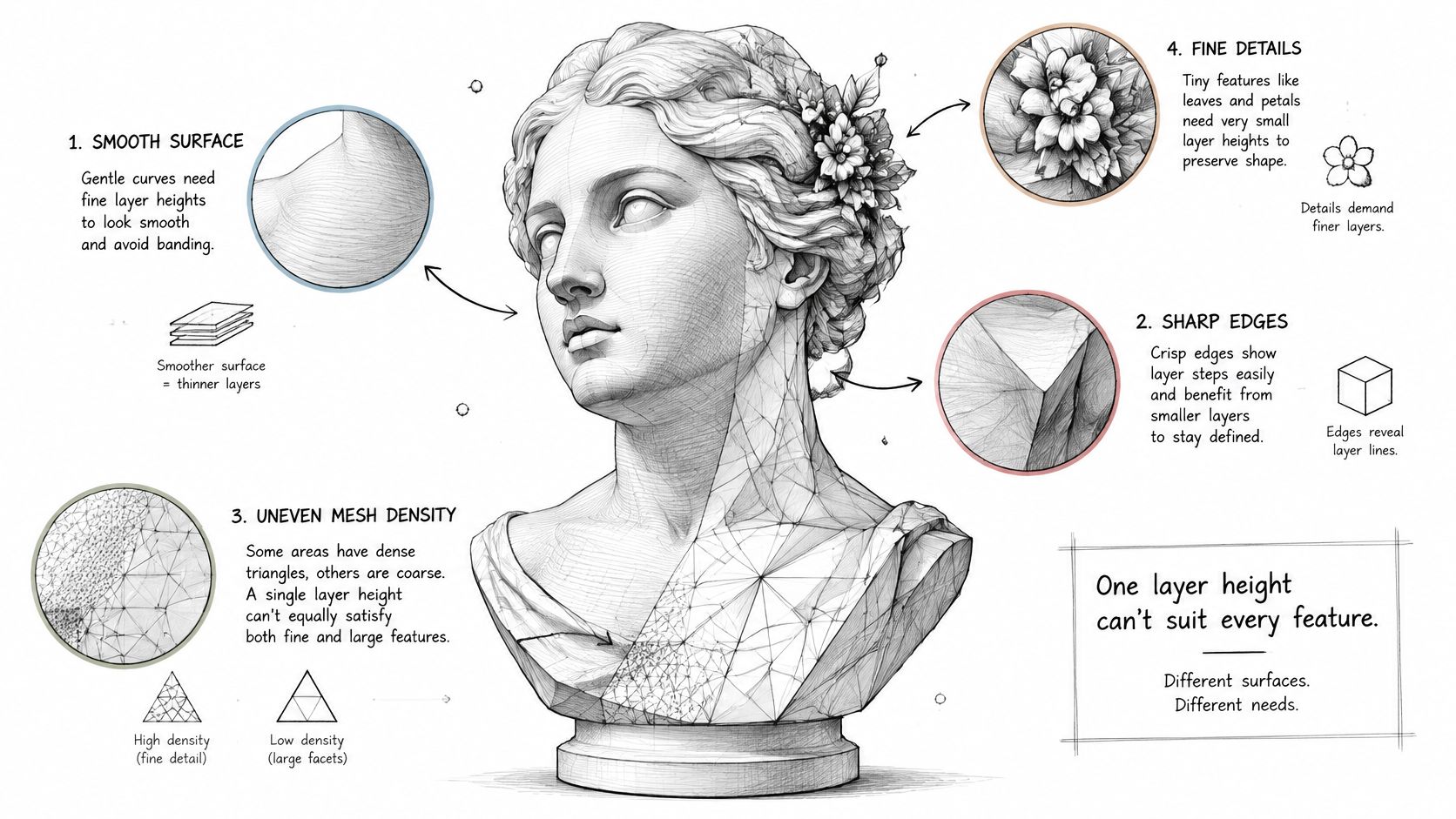
The workflow that works runs in a fixed order.
Fix the mesh before you touch the slicer. Check that it's watertight and free of inverted faces, then even out the surface with remeshing or retopology. A patchy triangle distribution prints as patchy surface artifact that no layer height can fix. Sculpty's one-click remesh handles this step for exported assets, and the same idea applies in any mesh tool you prefer.
Decide which faces anyone will see. The front of a bust, the top of a relief plaque, the outward face of a wearable. Mark those regions. Everything else can print coarser.
Use variable layer height in the slicer. Refine the curved, visible regions and coarsen the flat bases, the interior and the hidden back. Most current slicers expose this as a per-height modifier curve rather than a single number.
Stair-stepping shows worst on shallow slopes near horizontal, where each layer advances a long horizontal distance and leaves a wide tread. Steep walls and vertical faces show almost nothing. Thin raised relief needs enough layers through its height to form crisply, so a 0.6 mm tall emblem at 0.30 mm layers becomes two smeared bands instead of a shape.
A web viewer can't show any of this. It renders a smooth surface with no slicing at all, so a model that looks flawless in the browser can arrive on the plate with visible ridges across the cheekbone. Check the slicer preview before committing filament.
If you're starting from a photograph or a sketch rather than a prompt, the AI image to 3D model workflow covers how the source image shapes mesh density. And when you're comparing conversion routes for flat artwork, the Img2stl tool listing on AI Tool Seekers is a sensible place to see the options side by side before you commit to one pipeline.
Export as STL or 3MF from the studio into the slicer, then preview the zones you set before printing.
Layer Height for Resin Printers
Resin machines run the same time-versus-detail trade, expressed in micrometres. The nozzle rules don't transfer, because there's no nozzle setting the extrusion width. Your floor is the printer's supported range and the resin's behavior at that thickness.
A 2024 orthodontic study compared digital light processing and stereolithography at layer thicknesses of 25, 50, 100 and 175 µm (PubMed study on DLP and SLA accuracy). Horizontally printed DLP models at 175 µm had a mean deviation of 0.015 ± 0.005 mm, while SLA models at 25 µm came in at 0.011 ± 0.005 mm. Seven times the layer thickness, four thousandths of a millimetre apart on that measure.
Printers in the field reflect similar ranges. A 2025 comparison of low-cost DLP and LCD resin printers used a 100 µm layer height, with the tested machines offering adjustable layer-thickness ranges between 50 and 150 µm, and one model supporting 22 to 150 µm (Biomimetics comparison of low-cost resin printers).
Surface roughness responds more directly to thickness than dimensional accuracy does. One process study reported minimum surface roughness of 0.242 micrometres at 50-micrometer layers, and found roughness rising from 7.861 micrometres at 0.1 mm to 28.012 micrometres at 0.7 mm as layers thickened, alongside declines in hardness and tensile strength (Journal of Materials Engineering and Performance study).
Start from the range your printer lists. Treat 50 µm as the finer option and 100 µm as the general one, and check the slicer's time estimate before committing to a 12-hour run. Then print the same small test at both thicknesses in your planned resin, measure the critical feature, and pick from measurement rather than the marketing sheet.
Confirm Your Layer Height With a Test Print
Everything above narrows the choice. A coupon settles it. Here's the procedure I use, in order.
- Name the feature that must work. Write it down as one of four: surface, fit, strength or time. A bracket that must survive a load is a strength part. A display bust is a surface part. The answer decides which row of the goal table you're testing.
- Print a small coupon or a scaled slice at two layer heights, typically 0.10 mm and 0.20 mm, using the nozzle and material you'll run. A scaled slice of the part beats a generic cube, because the failure you care about lives in your geometry.
- Measure the critical feature with calipers and inspect the surface under good light. Holes, bosses and threads get measured. Surfaces get tilted toward a window, where stair-stepping is unmistakable.
- Record the print time for each version. Time is the cost you're paying for detail, so write it next to the measurement rather than estimating it later from memory.
- Choose the thickest layer that meets the requirement and save it as a profile named for that material and nozzle combination.
The coupon matters because layer height changes dimensions in ways that depend on your material, your cooling and your machine. Two printers running the same file at 0.10 mm can land on different hole diameters. A twenty-minute test replaces a guess with a number, and the number is yours.
Export from the studio as STL or 3MF, then run it through the same slicing software for 3D printing you'll use for the final part, so the test and the print share a profile instead of a hope.
Layer Height Problems and How to Fix Them
Read the symptom first, then work back to the setting behind it. Changing one variable per reprint is the only way to know which fix worked, so resist the urge to adjust flow, speed and layer height in the same run.
Stair-stepping on curves is the most common complaint, and it traces to slicing itself: a curved wall gets approximated by stacked flat slices. Each layer is a flat slice, so the step height equals the layer height, while the horizontal tread between steps equals the layer height divided by the slope, which widens sharply on shallow surfaces. Dropping to 0.10 mm or switching to variable layer height on the curved regions addresses it directly.
Sagging or ridged overhangs come from the same geometry problem rotated 90 degrees. Each layer must extend out over the one below, and a thick layer has less overlap to anchor to, so it droops before it cools. Lowering the layer height or rotating the part so the overhang faces the fan both work.
Fine layers that string usually trace to flow and temperature. Very thin layers move slowly, the nozzle sits over the part longer, and ooze accumulates on every pass. Tune temperature and retraction before you go finer, or you will blame the setting for a calibration gap.
Weak or flaky layer bonds at thick layers mean the new bead could not melt into the one beneath it. Lower the layer height and check that the print temperature suits the filament.
Threaded features deserve their own note, because layer height alone will not explain the error. A 2025 design-of-experiments study on FDM found that layer height, nozzle diameter and bed temperature significantly affected dimensional accuracy, with deviations reaching 4% for screw diameters and 7% for nut diameters (design-of-experiments study on FDM dimensional accuracy). For a 10 mm thread that is the difference between a cap that bites and one that spins.
| Symptom | Likely cause | Fix |
|---|---|---|
| Stair-stepping on curves | Layers too thick for the curvature | Drop to 0.10 mm or use variable layer height on curves |
| Sagging or ridged overhangs | Thick layers on steep faces | Lower layer height or reorient the part |
| Draft takes too long | Layer height finer than the goal needs | Raise to 0.28-0.30 mm on a 0.4 mm nozzle |
| Stringing or oozing at fine layers | Flow and temperature not tuned for slow layers | Tune temperature and retraction before going finer |
| Weak or flaky layer bonds | Layers too thick for cooling or the nozzle | Lower layer height and check print temperature |
| Holes or threads undersized | Layer height and flow not calibrated for the feature | Print a calibration coupon and adjust |
Triage order: fix extrusion and temperature first, then layer height, then geometry. Layer height changes mask a badly tuned flow setting for about one print, then the problem comes back.
Some fixes need one reprint. Stair-stepping, draft speed and overhang sag all fall into that group. Anything touching a hole, a thread or a mating face needs a coupon and a measurement, which makes it a calibration run.
Match the fix to the feature that matters. Curves and display surfaces are surface problems, threads and mating faces are fit problems, weak bonds are strength problems, and a slow draft is a time problem. Knowing which category you are in keeps you from burning a weekend on a fifteen-minute decision.
Sculpty is a browser-based 3D AI studio that generates meshes from text, images or multiple photos and then gives you the cleanup tools a print-ready asset needs: one-click remeshing and retopology to even out triangle density, PBR texturing, and export to STL, 3MF, OBJ and GLB so the file lands in your slicer as you built it. That matters for this topic because feature-aware layer heights only work when the mesh surface is consistent enough to slice cleanly. Visit Sculpty to generate a model, remesh it, and export it straight into the profile you calibrated today.