3D Printing Textures: Complete Practical Guide for Makers
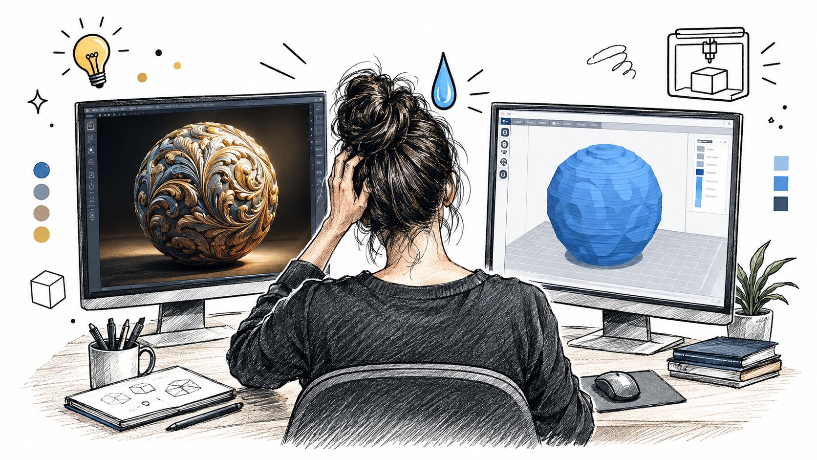
A textured 3D model can look perfect on screen and still come off the printer as a smooth lump. The rough stone in your render may be nothing more than a roughness map. The fine ridges in an AI-generated material may exist only as shading. Once the slicer receives the mesh, it can't print information that was never encoded as physical geometry.
That gap between digital texture detail and printable relief is where most failures begin. Successful 3D printing textures require you to design for the nozzle, resin cure, layer structure, orientation, and the way a person will touch the finished part. The question isn't whether a texture looks convincing in a render. It's whether the texture survives export, slicing, fabrication, cleaning, and use.
Table of Contents
- Why Your Textured 3D Prints Fail in the Real World
- Designing Emboss and Engrave Details for FDM and Resin
- Understanding Tactile Perception and Roughness Science
- Converting PBR Maps and Displacement Data to Printable Geometry
- Process-Specific Texture Optimization for FDM vs Resin Printing
- Validating Texture Survivability with Test Prints
- Real-World Applications and Advanced Texture Techniques
Why Your Textured 3D Prints Fail in the Real World
You've probably seen the failure in its most frustrating form. A digital sphere has convincing pores, chipped edges, and layered mineral detail. The lighting catches every ridge. You export the object, open it in a slicer, and print it. The result has the correct silhouette, but the surface feels almost completely smooth.
The file didn't necessarily break. The texture was often never part of the printable model. A PBR material can define color, roughness, and simulated bumps without changing the object's outer surface. A height or displacement map can alter geometry, but only if the workflow applies it to a sufficiently dense mesh and the resulting features remain large enough for the chosen process.
Rendering detail and physical detail are different assets
A render interprets tiny tonal changes as form because light and shadow do the work. A printer needs a continuous, watertight surface with ridges and recesses that can be deposited or cured. If a relief is too fine, the slicer may merge it with neighboring geometry, reduce it to a barely visible line, or remove it during mesh processing.
The same problem appears at larger scales when texture is placed on a curved surface without considering orientation. A pattern that reads clearly from one camera angle may align poorly with layer paths, supports, or the direction of hand contact. Texture survivability depends on geometry, feature scale, material, and process together.
Practical rule: Treat every visible texture as either render-only, printable geometry, or a detail that needs a physical test. Never assume it belongs in all three categories.
Failure analysis is useful here because it forces you to connect the visible defect to a specific design or process decision. A guide to failure mode analysis in materials can help structure that thinking without reducing every failed print to a slicer setting.
The most reliable mindset shift is simple. Design the broad surface first, then decide which details need to cast a real shadow or create a tactile change. Keep color variation and subtle roughness in the material when they're only visual. Convert information into geometry when someone must feel it, measure it, paint it, grip it, or see it under changing light.
Designing Emboss and Engrave Details for FDM and Resin
Physical texture starts with a relief decision. Embossed details rise above the surface, while engraved details cut into it. Both can work, but each creates different risks around edge definition, support contact, cleaning, and accidental merging.
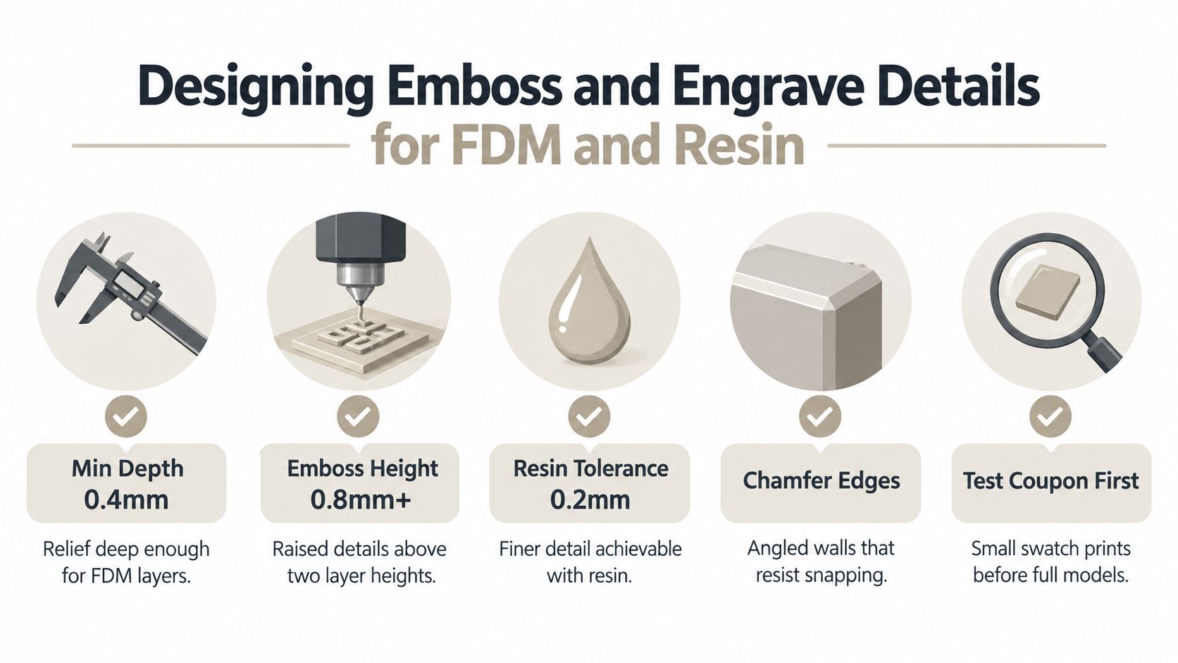
Start with a clean base surface and create relief from a controlled grayscale or procedural mask. In Blender, a Displace modifier can work for broad forms, while a Boolean modifier is more dependable for clean logos, lettering, and repeated grooves. Sculpting is effective for organic bark, stone, or leather, but the resulting mesh needs inspection before export. For image-driven work, a workflow such as creating an STL file from an image can provide a starting point, but it still requires scale and print validation.
Make relief survive the tool, not just the viewport
For FDM, avoid treating a fine bump map as a finished texture. Extrusion width and layer structure limit what the printer can separate. Broad, continuous ridges usually survive better than isolated spikes, tiny pits, or sharp changes that ask the nozzle to start and stop repeatedly.
Resin printing can preserve finer geometry, but it introduces its own failure modes. Narrow grooves may close during exposure or become rounded during washing and curing. Raised details can also snap during support removal, especially when they sit on a face that receives direct support contact.
Use these design choices as a starting framework:
- Prefer radiused transitions: Small fillets or chamfers reduce fragile knife edges and make raised features less likely to chip.
- Separate neighboring features: Leave enough open space for the slicer and material to preserve the gap. Dense patterns often merge before you notice the problem in the preview.
- Orient for the texture: A grip pattern should reinforce the direction of force. A decorative pattern should face away from supports and avoid placing its most visible relief across unfavorable stair-stepping.
- Keep critical geometry intentional: Don't convert every pixel of a height map into a bump. Simplify low-value detail and preserve the features that affect touch, function, or recognition.
- Test a patch: A small swatch tells you more than a beautiful viewport screenshot. Include a flat region, a slope, raised relief, recessed relief, and a transition between smooth and textured surfaces.
Engraving needs particular care. A shallow groove can disappear into the top layers of an FDM print, while a deep narrow cavity can trap resin or become difficult to clean. Embossing has the opposite risk. A proud feature may print clearly but become vulnerable to abrasion, support scars, or accidental contact during handling.
The most reliable texture designs use sloped walls, rounded corners, and repeated forms with a clear minimum scale. They also account for the face that will be printed first. Texture isn't neutral to orientation. The same mesh can show different edge quality depending on whether a ridge runs with, across, or diagonally to the layer paths.
Understanding Tactile Perception and Roughness Science
A texture that looks rough in a render can feel smooth in the hand once its smallest features collapse at print scale. Touch responds to element size, spacing, regularity, wavelength, and contact area, so a visually busy AI-generated PBR pattern may produce little usable relief after conversion into physical geometry.
A Journal of Neurophysiology study reported a Weber fraction of 0.19 for roughness judgments, showing a measurable relationship between physical differences and tactile discrimination (study on roughness perception). Participants generally judged textures with large spatial periods as rougher. Small elements could also feel rougher than larger elements with the same wavelength, which makes overall pattern density an unreliable guide when judging a printed surface.
At prototype scale, preserve the features that survive the nozzle or resin process. A height map may contain convincing micro-variation, yet the printed part may retain only the broader peaks and valleys. Those surviving features determine the hand feel.
Pattern arrangement changes the hand's response
Regular, directional patterns and irregular, evenly distributed patterns create different tactile signals. The same study found that irregular isotropic arrangements produced higher roughness estimates than regularly arranged anisotropic patterns at the same wavelength. A random pebble-like pattern can therefore feel rougher than a neatly aligned rib pattern with comparable broad spacing.
Contact density creates another counterintuitive effect. Closely spaced elements increase the area touching the skin and can make a surface feel smoother. A dense stipple may feel polished or soft, while a less crowded pattern with distinct peaks can feel abrasive. At small print scales, overpacked relief also tends to merge, reducing the contrast between rough and smooth regions.
Tune texture to hand motion and use case, not visual complexity alone.
For a grip, directional ribs should follow the expected force so the fingers can resist sliding. For a tactile graphic, distinct regions and clear boundaries matter more than decorative micro-detail. For a decorative object, controlled irregularity can produce a richer hand feel, provided the contact density does not flatten the surface response.
Validate the result physically. Print competing patterns at the intended scale, then assess them with the same finger motion and pressure. A pattern can look aggressive while feeling weak, or appear subtle while producing a strong tactile signal. That comparison exposes which parts of the digital texture survive printing.
Converting PBR Maps and Displacement Data to Printable Geometry
A PBR map is a description of appearance. A printable relief is a change in the boundary of the object. Converting one into the other requires filtering, scaling, and mesh cleanup rather than a simple export.
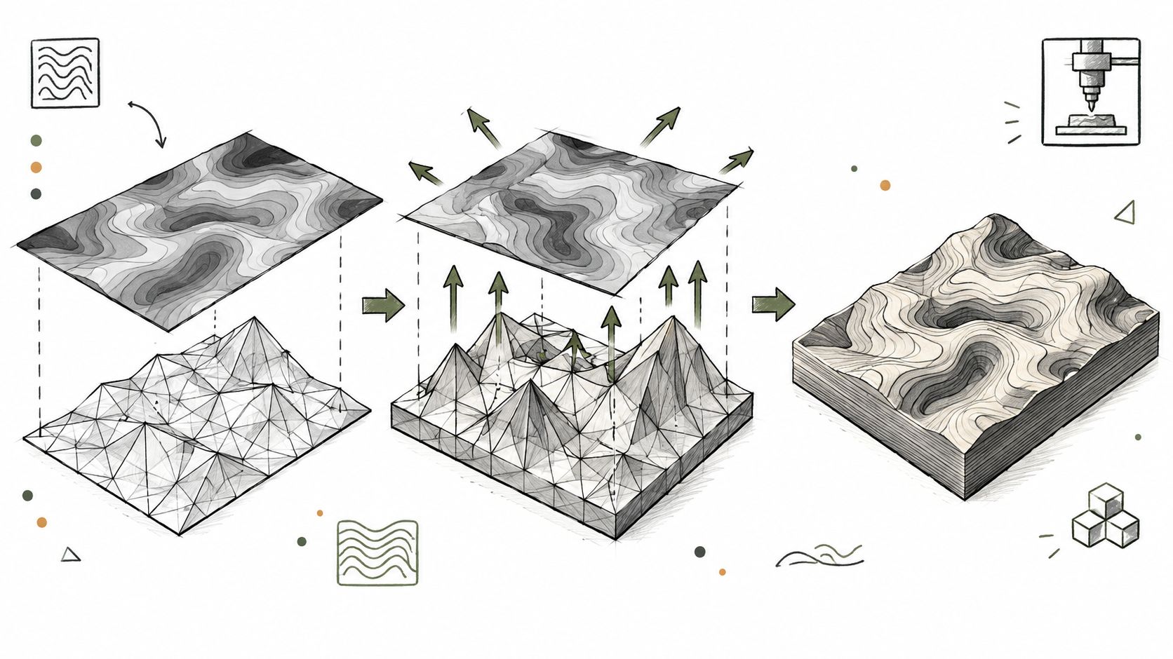
Begin by separating the maps. Color belongs in the material or a color-capable print workflow. Roughness is usually visual only. Height, normal, and displacement information deserve inspection because only some of it should become actual geometry.
A reliable conversion sequence
Classify the detail. Mark broad shape, medium relief, and micro-detail separately. Broad shape should affect the model. Medium relief may become printable geometry. Micro-detail often belongs in the render unless the target process can resolve it.
Apply displacement selectively. Use a grayscale height map on a mesh with enough surface resolution. Limit the displacement range so it doesn't distort the silhouette or create self-intersections. A dense procedural texture isn't a substitute for a clean, controlled relief.
Remesh and inspect. Remeshing can distribute polygons more evenly, while retopology can make the asset easier to edit. Check for non-manifold edges, inverted normals, thin shells, trapped internal surfaces, and disconnected islands before exporting an STL or 3MF.
Preserve meaningful edges. Decimation is useful when the file becomes unwieldy, but aggressive reduction can erase the very ridges you intended to print. Compare the simplified mesh against the original at the intended physical scale, not only in a zoomed-out viewport.
Preview in the slicer. Look at layer-by-layer paths and the actual toolpath preview. A relief that looks continuous in the modeler may be skipped, fused, or represented by a single inconsistent line in the slicer.
A useful rule is to bake geometry only when it changes the physical experience. Keep purely visual cues in PBR maps for faster rendering and cleaner dimensions. This matters especially for AI-generated materials, which can invent semantically convincing pores, scratches, and fibers without producing geometry that a printer can reproduce.
For reference-driven assets, tools that turn photos into 3D video can help you inspect an object from changing viewpoints before deciding which surface information deserves physical treatment. The final manufacturing file still needs mesh validation and print-scale testing.
A browser-based workflow such as texturing a 3D model can be useful for generating and reviewing material directions, but don't confuse a finished textured GLB with a verified printable relief. Export the geometry, scale it, slice it, and test it.
Process-Specific Texture Optimization for FDM vs Resin Printing
Texture that survives on screen can disappear at print scale. FDM may turn fine PBR height information into layer ridges or uneven extrusion, while resin can reproduce smaller relief and then soften it during support removal, washing, or post-curing. Choose process settings according to the smallest physical feature that must remain visible or tactile.
For near-planar FDM faces, ironing can improve the top finish. A published study found that ironing at 45°, with 0.15 mm line spacing and 20% ironing flow, produced the lowest reported Ra and Rz in its tested setup. Increasing line spacing from 0.05 mm to 0.15 mm reduced both measures consistently in that study (FDM surface texture characterization).
Ironing only suits surfaces that the nozzle can traverse cleanly. On slopes, recesses, and sculpted relief, it may create overfilled ridges, scars, or dimensional growth. Keep delicate height-map detail out of ironing paths unless a preview confirms that the toolpath preserves it.
Resin printing gives finer control over small features, but exposure and post-processing decide whether those features remain open. A Taguchi-based study tested 0.02 to 0.04 mm layer thickness, 3 to 5 seconds of exposure, and 0° to 45° printing angles. Its lowest areal roughness occurred at 0.02 mm layers, 3 seconds of exposure, and 0° orientation. Post-curing reduced roughness by approximately 8% to 11% across the tested groups (resin printing surface roughness study).
| Parameter | FDM/FFF optimization | Resin, SLA/DLP optimization |
|---|---|---|
| Layer structure | Select a layer height that preserves the relief profile, then orient visible texture to limit damaging stair steps. | Use the finest layer setting that the printer and exposure calibration can resolve. The tested low-roughness condition used 0.02 mm layers. |
| Top-surface finishing | Apply ironing selectively on near-planar faces. The tested combination used 45°, 0.15 mm spacing, and 20% flow. | Expect curing to change the surface. It may smooth broad areas while rounding grooves or closing small openings. |
| Orientation | Align ribs and visible slopes with their intended force direction and appearance. | Screen orientation for support marks and stair-stepping on cosmetic faces. The tested low-roughness condition used 0° orientation. |
| Detail strategy | Favor continuous relief that the nozzle can deposit consistently at the chosen scale. | Add narrow detail only after exposure, washing, and curing checks show that it remains distinct. |
| Validation | Compare identical samples under fixed settings and inspect the actual printed relief. | Keep resin temperature, wash time, support design, and cure dose consistent between samples. |
Set these constraints before converting AI-generated PBR maps into geometry. A 3D print settings guide can support initial setup decisions, but the workable values depend on the machine, material, geometry, and intended texture experience.
Validating Texture Survivability with Test Prints
A textured handle can look convincing in a render and still feel nearly smooth after printing. A full model will not tell you why. It combines relief scale, orientation, exposure, support placement, and post-processing, while consuming material before you isolate the failure.
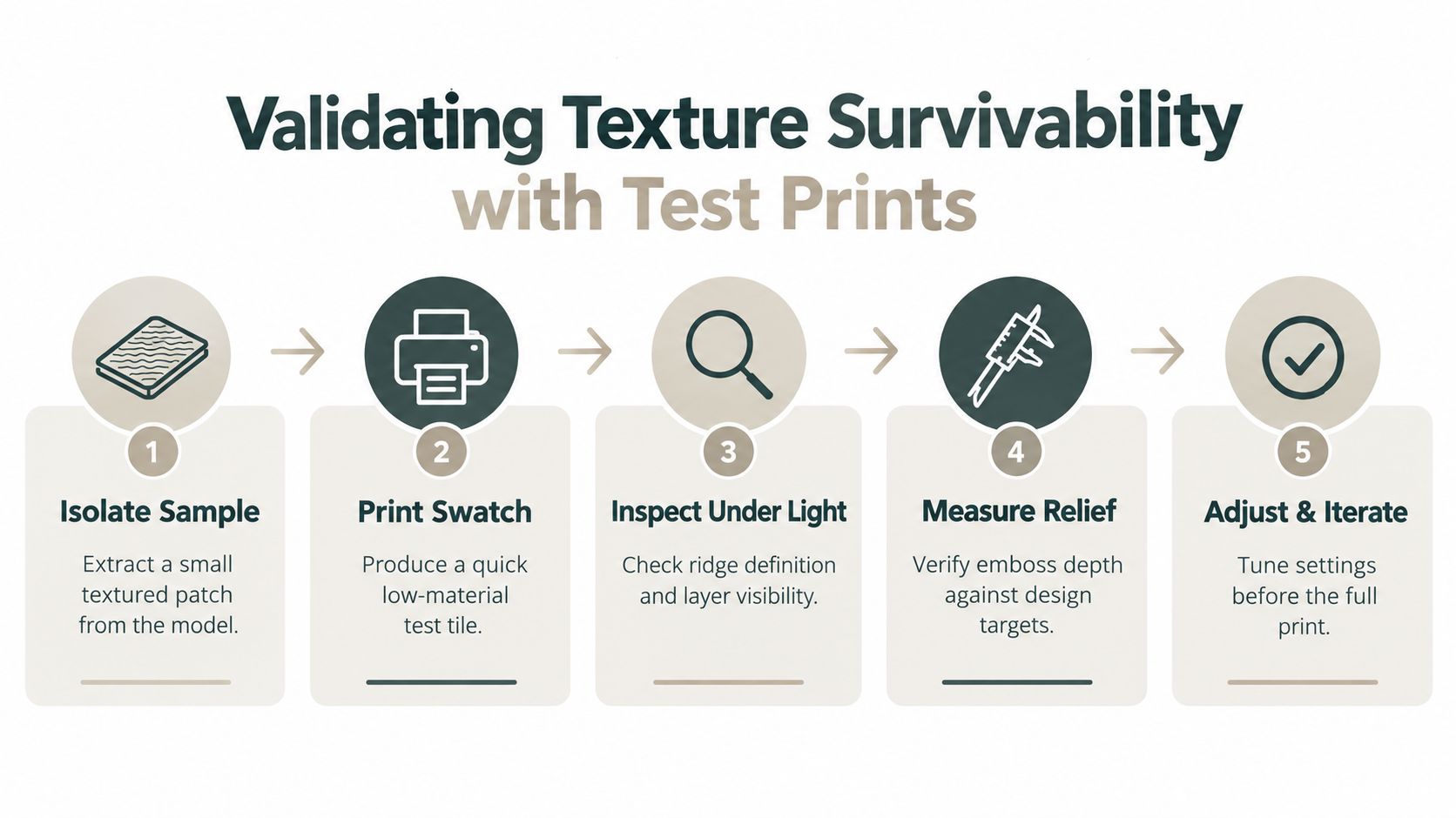
Create a texture coupon around the surface behavior you need to preserve. Include a smooth control area, raised and recessed features, a directional pattern, an irregular pattern, a curved section, and a support-sensitive region. Match the final object's base geometry and print orientation closely enough that the coupon exposes the same scale and process limits. AI-generated PBR maps often contain fine height changes that disappear when converted into printable relief, so include features at several practical sizes.
Run a small, controlled experiment
For FDM, fix nozzle temperature, bed temperature, speed, filament batch, orientation, and cooling before comparing ironing or other surface parameters. The published FDM methodology recommends identical PETG coupons and replicated Ra/Rz measurements, as introduced earlier (surface texture measurement methodology). The same setup makes printer noise easier to distinguish from a genuine geometry or process effect.
Test at least three line spacings and three flow levels when ironing affects the result. Measure every coupon with identical filtering and cutoff settings. A roughness value has little meaning if the measurement scale changes between samples.
For resin, print the same textured calibration object at selected layer heights. Hold resin temperature, wash duration, support strategy, and post-cure dose constant. Check broad roughness alongside feature fidelity. A smoother coupon may have rounded or closed the grooves that gave the texture its function.
Use this pre-flight checklist:
- Isolate the sample: Extract a representative patch instead of printing the complete model.
- Print the swatch: Use the intended material and orientation, not a convenient substitute.
- Inspect under changing light: Raking light exposes ridges, scars, stair-stepping, and merged details.
- Measure the relief: Confirm that raised and recessed features still match the design intent.
- Test the hand feel: Grip, slide, press, or trace the surface as the finished object will be used.
- Adjust one variable at a time: Change geometry or process settings deliberately so each result remains interpretable.
Keep a physical reference library. A small box of labeled texture coupons gives you reliable comparisons when a new AI-generated surface reaches the slicer.
The useful result is a repeatable relationship between the intended map, printed geometry, tactile response, and manufacturing process. Once you know which relief survives on your equipment, you can edit future surfaces for physical performance instead of trusting the screen preview.
Real-World Applications and Advanced Texture Techniques
A textured print can look convincing in a render and fail the first time someone grips, washes, slides, or presses it. The useful surface is the one whose geometry survives the print process and continues to perform after handling. AI-generated PBR maps often contain fine color and roughness variation that reads well on screen but produces no reliable physical relief.
Start with the job the texture must perform. A tool grip needs resistance to sliding without creating painful pressure points. Directional ribs suit a grip loaded from one direction, while an irregular pebble pattern can distribute contact across the hand. A shallow crosshatch may work when the user needs traction from several angles. Check the spacing and height at print scale, because a PBR normal map can suggest deep texture without containing geometry that a slicer can reproduce.
Decorative surfaces need a different treatment. Keep a raised border or selected grooves as physical features, then leave smaller color and roughness changes in the render or material definition. This preserves visual richness without covering the object with fragile micro-relief that will merge, soften, or disappear during printing.
Texture can carry information
3D-printed texture can serve as a tactile communication medium, not only as decoration. A 2023 study evaluating printed tactile content for people with visual impairments tested six materials, four line widths, seven feature heights, and four samples for every configuration at two measurement points, producing 1,344 measurements (study of printed tactile content).
The same study reported that line widths between 0.8 mm and 1.2 mm provided the most reliable adhesion for tactile graphics. 0.4 mm was the maximum feature height that did not compromise adherence in the tested configurations. Its comparison of rectilinear and concentric infill patterns produced different overall average results, 49.94% for one surface configuration and 43.12% for the other, across 54 samples per surface type.
These results give AI-generated texture a practical constraint. Preserve the cues that need to be felt, widen or simplify them when necessary, and remove relief that falls below the printer's dependable feature scale. Infill can create distinguishable tactile cues, but only when the resulting geometry remains open, attached, and legible.
Function can matter more than visual smoothness
A smoother measurement does not guarantee better performance. Research on laser-SLA microchannels found that orientation changed channel-floor roughness, tortuosity, wetting behavior, and fluid-flow speed. A single roughness value could not describe all of those effects. Repeated press-fitting and removal can also alter PET-G housing surfaces, so printed texture may change during service.
For seals, sliding interfaces, biological contact, fluid movement, and press-fit assemblies, inspect texture direction, contact behavior, and wear. A polished appearance under a lamp says little about whether the relief still works after repeated contact.
Sculpty provides text-to-3D and image-to-3D generation, prompt-driven PBR texturing, remeshing, retopology, and exports including STL, OBJ, GLB, and 3MF. Use these tools to explore surface ideas quickly, then convert only meaningful visual cues into controlled geometry. Print a small coupon before committing the full model.
Choose one texture that must be felt and one detail that only needs to be seen. Visit Sculpty to generate and texture the asset, export the geometry, and include a print-scale validation step in the workflow.